- 1 x 5 Channels 4-20mA Analog Output
- 1 x 8 Channels Digital 5Amps 250VAC/30VDC Relay Output
- 1 x 8 Channels 0-20mA Analog Input
- 1 x 8 Channels 12-275 AC-DC, 60mA Digital Optocoupler Input
- Supports 2 x 10/100Base-T(X) ports
- Embedded web interface for ease of use
- MQTT Publisher with different data transfer options
Parsed Data as Data Objects
Parsed Data as Modbus Frame
- HUR can send Data to Server and MQTT Server can remotely control Output Versions of HUR Devices in the same time
- Logic Function commands available to make field automation based on I/O status
- Easy to follow Device Status on web interface
- Easy to follow Device Parameters such as Device Up Time, Modbus read counter etc. on web interface
- Easy to follow Modbus data packages on web interface
- Up to 10 client connection in Server Mode
- DHCP Server Capability
- Device Address changeable via web interface
- Output configuration can be defined by user for restart
- Output values can be saved and applied during auto restart
- I/O Mirror functionality: Device can duplicate output from a Modbus input device
- Black List and White List based IP Filter in TCP Server Mode
- Firmware Upgrade over Web
- 2 firmware storage capability on same device (1 active only)
- 100 - 240V AC (120 – 370V DC), 50Hz to 60Hz AC wide range power input
- Wide operating temperature range from -25 to 70 °C
- Rugged Metal IP-40 housing design
- DIN-Rail mounting
ETHERNET TECHNOLOGY
Ethernet Standards
IEEE 802.3 for 10Base-T
IEEE 802.3u for 100Base-T(X)
IEEE 802.3x Flow Control
Mac Table
1K MAC address entry
Processing
Store-and-Forward
Memory
448K bits packet buffer memory
NTP TIME SYNCHRONIZATION - HUR
NTP is used to syncronize device time. Device checks if NTP time server is available in every 10 seconds after repower. Device synhcronizes its time if NTP time is available and stops checking after successfull synchronization.
All I/O Logic Function check times updates based on new time automatically.
MODBUS DETAILS - HUR OUTPUT MODELS
Protocol
Modbus TCP
Modbus Address
Default value is 0x01
Changeable via Web Interface
Save Output Values Before Auto Restart
Default enabled and when system auto restarts the values are saved and applied after restart
Save Output Values and Apply on Power Up
Default disabled, user can activate and enter parameters for each output individually
Changeable via Web Interface
I/O Mirror Functionality
Default disabled
If enabled, device can read input value of remote HUR device and duplicate those values as output
Monitoring Parameters
Modbus Read counter
Time counter (in seconds)
FW version
Device Up Time
TCP packages
MQTT DETAILS - HUR
MQTT Publisher can be enabled and can be used in parallel with Modbus conversion (or stand alone)
MQTT Connection
Broker IP and Port can be entered
Client ID , User name and Password can be set
Publish Topic and Subscribe Topic can be defined from web interface
Data Send Interval
User can set Data send interval in seconds
Default is 60 seconds and HUR will send meter data to MQTT server in that interval
NTP Server
NTP server time will be added to each MQTT message
Data Format
There are 2 predefined formats
Parsed Data As Objects: Sends I/O values in ASCII readable fromat
Parsed Data as Modbus Frame: Send just like the response of Modbus query as hex data (smaller data size)
I/O LOGIC FUNCTIONS
All versions of HUR Series Modbus TCP Remote Input/Output (I/O) Devices support I/O Logic Functions which can be used to make field automation by using HUR Series itself in the field. As an example, device can be programmed to Turn ON Output or send status of input values to MQTT server or LoRaWAN Server when an input dedected. There are many combinations available.
I/O Logic Commands
16 commands available in Multi Slot Models
8 commands available in Single Slot Models
Condition Slot and I/O
HUR can check programmed input or output of selected slot. This can be any of the available slot (Analog Input, Digital Input, Analog Output or Digital Output)
Condition Command
For Analog Input and Analog Output: HUR can check if the selected I/O value is Higher or Lower than user specified value
For Digital Input and Digital Output: HUR can check if the selected I/O value is ON, OFF or its State Changed (from ON to OFF or OFF to ON)
Condition Duration
HUR can check the command for user defined duration and function is only triggered when command is true for specified duration
Result Slot and I/O
This is the affected input or output number of slot for triggered command. This can be any of the available slot (Analog Input, Digital Input, Analog Output or Digital Output)
Result Command
For Digital Output and Analog Output: HUR can set output to specific value. It can be On, Off or State Change for Digital Output model and can be user defined value for Analog Output Model
For All Slot Models: HUR can send MQTT message or LoRaWAN message for specified slot when command is triggered
Wait Before Next Check
Once the command is triggered, HUR can wait for next check of command based on user defined duration
Examples
Examples applies to models with the mentioned hardware
HUR can send MQTT message for selected slot if an Analog Input Value is Higher than 10mA.
HUR can send LoRaWAN message for selected slot if an Analog Input Value is Lower than 10mA.
HUR can set Output On for selected Digital Output slot if a Digital Input value is OFF
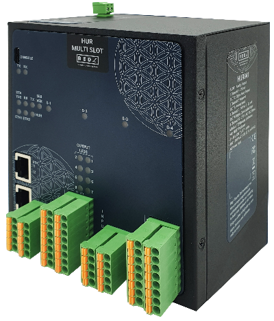
CONNECTORS AND PORTS - MULTI SLOT
Console Port
USB Type C or Micro USB connection for LOG in 115200 baud
10/100T(X) RJ45 Ports
Ethernet Connection on 2 ports
Reset Buttons
Reset to Client and Reset to Server Operating modes buttons
I/O TERMINAL AND INDICATORS - 1 Slot x 5 Channel Analog Output,1 Slot x 8 Channel Digital Relay Output, 1 Slots x 8 Channel Analog Input, 1 Slots x 8 Channel Digital Optocoupler Input
SLOT 1
I/O Connectors
Terminal Connectors
Analog Outputs: 1 Slot x 5 Channel 4-20mA Analog Output
5 Analog Outputs total 10 connection pins.
4-20mA Analog Output designed for 24V 250ohm load or 12V 125ohm load.
Over Voltage Protection
Analog Output:
40V
SLOT 2
I/O Connectors
Terminal Connectors
Digital Outputs: 1 Slot x 8 Channel 5Amps 250VAC/30VDC Digital Relay Output
8 Channel Output terminals and polarity is not important. 2 pins for each connection and total 16 connection pins.
Maximum 5 Amperes 250VAC/30VDC for each channel.
Dielectric Strength
3kV dielectric strength (between coil and contacts)
Meets IEC61131-2 reinforce insulation
Output Status LEDs
Shows which pin is ON and OFF for Digital Output versions.
SLOT 3
I/O Connectors
Terminal Connectors
Analog Inputs: 1 Slot x 8 Channel 0-20mA Analog Input
Polarity is important and all inputs references to Common point.
2 Common points 8 Analog Inputs total 10 connection pins.
0-10V and 0-20mA Selectable during order (default is 0-20mA) Analog Input
Analog Input Features
16-bit resolution with no missing codes
Throughput: 250 kSPS
SLOT 4
I/O Connectors
Terminal Connectors
Digital Inputs: 1 Slot x 8 Channel 12-275V AC-DC, 60mA Digital Optocoupler Input
8 Channel Input terminals and polarity is not important. 2 pins for each connection and total 16 connection pins.
12-275 AC-DC, 60mA Digital Optocoupler Inputs.
Isolation
Digital Optocoupler Input:
4470Vrms 1min
Over Voltage Protection
Digital Optocoupler Input:
275V
LED INDICATORS - HUR MULTI SLOT
Power Indicator
Power LED
10/100T(X) Indicators
Activity LEDs:
ETH1, ETH2 and HUR (Activity of device itself)
System Indicators
Status LED,
Tx and Rx of data LEDs and Server LED
(LED ON: Server Operating Mode, LED OFF: Client Operating Mode)
Slot LEDs
S-1, S-2, S-3 and S-4: Turns On for 1 second and Turns OFF for 1 second under normal operation of I/O Interface.
Each LED corresponds to related I/O Slot.
Console Indicators
Tx and Rx of data LEDs
POWER - AC
Input Range
100 - 240V AC (120 – 370V DC), 50Hz to 60Hz Wide Range AC Power Input
Isolation
Fully Isolated >4200Vrms, 5mA 1 Min
Insulation
Class II
PHYSICAL AND ENVIRONMENTAL CHARACTERISTICS - MULTI SLOT - AC POWERED MODELS
Enclosure
Metal, IP 40
Dimensions
115 x 970 x 126 (w x d x h) mm
Weight
~700gr
Storage Temperature
-40 to 105 °C
Operating Temperature
-25 to 70 °C
Operating Humidity
5% to 95% Non-condensing
HUR841: Multi Slot, 1 x 5 Channels 4-20mA Analog Output, 1 x 8 Channels Digital 5Amps 250VAC/30VDC Relay Output, 1 x 8 Channels 0-20mA Analog Input, 1 x 8 Channels 12-275 AC-DC, 60mA Digital Optocoupler Input Modbus TCP Remote IO Device, 2 x 10/100 T(x) ETH ports, 100 - 240V AC (120 – 370V DC), 50Hz to 60Hz AC Power Input

