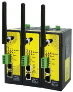
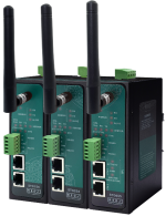
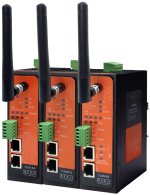
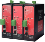
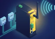
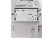
- 1 x 10/100 Ethernet port
- Plug and play design for EMH LZQJ-XC meters; direct replacement for Variomod XC modules for EMH meters
- Serial interface directly connected to the meter (isolated, up to 5000 VRMS isolation rating, up to 10 kVPK surge capability, overload and short-circuit protection, thermal shutdown)
- Embedded web interface
- Reads the EMH LZQJ-XC meter with IEC 62056-21 (Mode C) or DLMS/COSEM
- Reads 1 meter; Modbus TCP function only: Serial Electricity Meter to Modbus TCP Gateway (and MQTT Publisher)
- Up to 48 OBIS codes per meter profile; only the IEC 62056-21 and Generic DLMS profiles (DLMS/COSEM meters are read with the Generic DLMS profile)
- Negative meter values keep their sign; a value too large for the 32-bit register gives a fixed limit value
- Modbus TCP server with up to 10 clients at the same time
- Function code 03 (Read Holding Registers); every value is 32 bits = 2 registers, 48 values per meter row
- MQTT publisher with two data formats (OBIS VALUES AS OBJECTS and OBIS VALUES AS MODBUS FRAME), at the same time as Modbus
- 868 MHz LoRaWAN Meter Reader: the meter data is also sent to a LoRaWAN network server through a LoRaWAN gateway
- Radio band EU 868 MHz (Europe); the send interval is set by the user
- Built-in duty cycle check and payload size check: the device splits the data by the maximum payload size and the duty cycle block times, so the meters can be read at any interval
- Activation over the air (OTAA) or by personalization (ABP); Class A or Class C
- Adaptive Data Rate, selectable uplink data rate and Tx power level (EIRP), user defined LoRaWAN port, with or without ACK
- Device and LoRaWAN status on the LoRa Status page, including the latest LoRaWAN messages
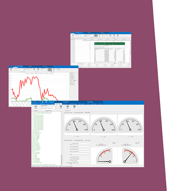
- Meter reading, Modbus communication and OBIS-to-Modbus mapping status, and the meter read-out data, on the web interface
- Device Status overview cards for the meters, Modbus, MQTT and LoRaWAN, each with a green, amber, red or grey dot
- White list or black list IP filter with up to 20 IP addresses (in the Modbus TCP function)
- DHCP server
- Firmware update over the web interface; 2 firmware banks in the device (1 active), the previous firmware can be started again
- Configuration backup and restore as a file
- No console connection for logs; the log goes to a UDP server
- Gets power directly from the meter (isolated, isolation voltage up to 1500 VDC)
- Operating temperature -40 to 85 C
- ABS housing, IP51, 105 x 45 x 27 mm (h x w x d)
LoRaWAN TECHNOLOGY - 868 MHz
Radio Band
EU 868 MHz (Europe)
Radio Module
pre-certified according to EN 300 220
Sensitivity
down to -138 dBm
Link Budget
up to 156 dB
Communication Distance
up to 15 km (line of sight)
Sensitivity, link budget and distance are the values of the radio module datasheet.
Tx Power Level (EIRP)
0 to 16 dBm, configurable
Uplink Data Rate
LoRa SF12 / 125 kHz / 250 bps to LoRa SF7 / 125 kHz / 5470 bps, or Adaptive Data Rate
Activation
Over-the-Air (OTAA) or by Personalization (ABP)
LoRaWAN Class
Class A or Class C
LoRaWAN Port
user defined (meter data; factory 3)
Transmission
without ACK or with ACK
LoRaWAN UPLINK DETAILS - LKM
After every join the gateway sends, in this order: a LoRaWAN time request (DeviceTimeReq) to set its clock, the status message (port 1), the OBIS details message (port 2, only if "Send OBIS Code Details as Status Message At Start" is on), then the meter data messages ("LoRaWAN Port", factory 3).
A step that cannot be completed in 5 tries or 180 seconds is skipped, so meter data is never blocked by the first steps.
Every message starts with the device ID (4 bytes) and one byte with the message type (0 = status, 1 = OBIS details, 2 = meter data) and the package number.
A message longer than the maximum payload is sent as several packages.
The byte layout of each message and a payload formatter for the network server are given in chapter 14 "LoRaWAN Communication Example" of the user manual.
ETHERNET TECHNOLOGY
Ethernet Standards
IEEE 802.3 for 10Base-T
IEEE 802.3u for 100Base-T(X)
IEEE 802.3x Flow Control
Mac Table
1K MAC address entry
Processing
Store-and-Forward
Memory
448K bits packet buffer memory
NTP TIME SYNCHRONIZATION - LoRaWAN Models
NTP Server
"NTP Server IP or URL", default pool.ntp.org
The clock is kept by the LoRaWAN radio module. From 10 minutes after start-up the unit compares it with the NTP time every hour and corrects it when the difference is 5 seconds or more (no restart). The clock can also be set from the Management page ("Set Device Time").
No battery for the clock: after a power cut set the time again, from an NTP server or with "Set Device Time".
METER READING DETAILS - LKM
Meter Rows
1 meter row (the meter the unit is plugged into)
Protocols
IEC 62056-21 (Mode C) or DLMS/COSEM; a DLMS/COSEM meter is always read with the Generic DLMS profile
Meter Type (DLMS)
Standard DLMS only
IEC 62056-21 Settings
IEC address, reading table code (0 to 9), init string (sent 0 to 4 times to wake up the meter), IEC meter line control (7_EVEN_1, 8_NONE_1, 8_EVEN_1)
DLMS/COSEM Settings
meter type, DLMS address, address size (1, 2 or 4 bytes), client type (Management, DataCollection, Electricity, End Customer, Public, ManufacturerSpecific_32), OBIS reference (short names or long names), authentication (Low Security with password, or No Security)
Query Interval
1 to 65535 s for each meter (shortest time between two readings; the real interval can be longer when many meters or long read-out lists are configured)
Time Out
1 to 30 s for each meter
OBIS Codes
up to 48 OBIS codes for each of the two profiles (IEC 62056-21 and Generic DLMS), set from the web interface
MODBUS DETAILS - LKM
Function Code
03 Read Holding Registers only
Register Size
every value is 32 bits = 2 registers; 48 values per meter row (OBIS index 0 to 47)
Address Rule
address = 2 x OBIS index (one meter row, starting at 0)
Request
an even number of registers, 2 to 124
Unit ID / Slave Address
Gateway Modbus Address, 1 to 247 (factory 1)
Byte Order
big-endian inside each register; word order set by "Modbus Word (Register) Swap"
Modbus TCP
port 502 (factory); 1 to 10 masters at the same time (factory 2)
Exception Responses
none - a request that cannot be served gets no answer
MQTT DETAILS - LKM
MQTT Publisher
in the device function, at the same time as Modbus; one message per meter row after a successful reading
Connection
broker IP or URL and port, client ID, user name and password, publish topic and subscribe topic; MQTT 3.1.1 over plain TCP (no TLS encryption), QoS 0
Data Send Interval
"Minimum Send Interval for a Parsed Data (in seconds)", 0 to 65535 s, factory 60 s - the shortest time between two messages of the same meter row
Data Format
OBIS VALUES AS OBJECTS (one JSON object per meter row, OBIS codes and values as text) or OBIS VALUES AS MODBUS FRAME (one hex string: the data part of a Modbus answer with all 48 values of the row)
Time
with the time from NTP every message carries the time as UTC Unix seconds
Broker not reachable
the gateway tries again at most once every 5 seconds and does not restart because of MQTT; meter reading, Modbus and the web pages keep working
WEB MONITORING DETAILS - LKM
Device Status
overview cards for the meters, Modbus, MQTT and LoRaWAN with a green, amber, red or grey dot; communication counters
Gateway Status
the result of the last readings and the value stored for every OBIS code, for the last read meter or a selected meter row
Meter Reading Status
the last 210 lines of the meter communication - the data received from IEC meters and the messages of the unit about the readings; the OBIS codes are typed as they appear in the read-out list of the meter
LoRa Status
device and LoRaWAN status, including the latest LoRaWAN messages
CONNECTORS AND PORTS - LKM616
SMA Antenna Connector for LoRa
1 Standard SMA female interface, 50 ohm
10/100T(X) RJ45 Port
Ethernet Connection on 1 port
Reset Button
Reset to Factory Default Settings Button
LED INDICATORS - 1xETH MODELS
10/100T(X) Indicator
Activity LED for Ethernet
System Indicators
Status LED,
Tx and Rx of data LEDs and Server LED
Server LED: ON when the device function is Serial IEC Meter to Modbus TCP Gateway, OFF when it is TCP/IP IEC Meter to Modbus RTU Gateway.
POWER - LKM DIRECT CONNECTED MODELS
Connection
gets power directly from the meter (isolated, isolation voltage up to 1500 VDC)
Insulation
1500 V DC for 1 minute, leakage < 1 mA
PHYSICAL AND ENVIRONMENTAL CHARACTERISTICS - LKM DIRECT CONNECTED MODELS
Enclosure
ABS, IP51
Dimensions
105 x 45 x 27 mm (h x w x d)
Weight
about 200 g
Storage Temperature
-55 to 125 C
Operating Temperature
-40 to 85 C
Operating Humidity
5 to 95 %, non-condensing
LKM616: 868 MHz LoRaWAN Meter Reader and Electricity Meter Protocol to Modbus Protocol Gateway with MQTT, 1 x 10/100Base-T(X) Ethernet port, direct connection to the meter, powered from the meter interface