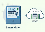
- Auto reads Electricity meters that communicates in IEC62056-21 standard (P1 Companion Standard on LKM124 model) and maps in predefined MODBUS register table
- Supports Up to 10 meters reading on RS485 Bus
- User defined initialization string can be sent before IEC62056-21 Mode C reading
- Configurable Modbus address via Modbus Commands
- Configurable Reading Period on IEC6056-21 or P1 Companion Standard side via Modbus Commands
- Configurable Reading Table Number on IEC6056-21 side via Modbus Commands
- Wide range power input: 5V – 24V (maz. 28V) DC
- Wide operating temperature range from -40 to 85 °C
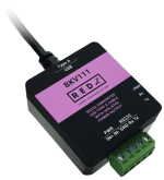
- Very Small form factor, only 2.1 x 4.2 x 4.4cm
- Customization of reading process and register tables based on client request
- Firmware upgradable over serial line
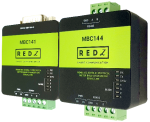
CONNECTIONS AND PROTOCOLS - LKM124
| Modem Side Connection
| Modem Side Connection | Meter Side Protocol |
| LKM124 | RS485 | P1 Interface
| P1 Companion |
MODBUS DETAILS - LKM RTU Models
Modbus RTU Address
Default value is 0x01
Changeable via Modbus Command
Reading Period on Meter Side
Default value is 10 (in seconds)
Changeable via Modbus Command
IEC62056-21 Protocol Meter Read Out Table
Default value is 0x30 = ‘0’in ASCII
Changeable via Modbus Command
IEC62056-21 Protocol Meter Reading Method
Reads each line of table and register data during reading
IEC62056-21 Protocol Meter Read Out Data
Date
Time
Import and Export Active Energy
Import and Export Reactive Energy
Reactive Energy in 4 Quadrants
Import and Export Maximum Demands
Active Power
Phase Currents for each phase
Phase Voltages for each phase
Frequency
Error Code
Extendable/Changeable via firmware change
Monitoring Parameters
IEC Read counter
Time counter (in seconds)
FW version
Query via Modbus Commands
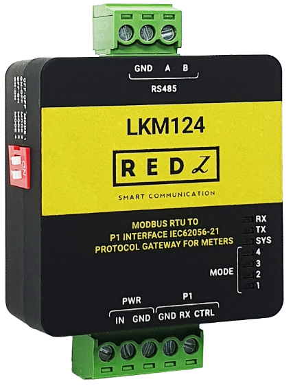
RS485 TERMINAL
RS485 Connector
Terminal Connector for 2 wire RS485 connection A - B and GND can be used as well.
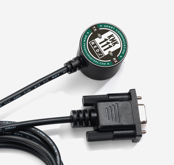
P1 INTERFACE
P1 Interface
Terminal Connector for 3 wire P1 Companion Standard connection: Data, Data Request and GND. Power input pins can be used to get power from P1 Interface.
INTERFACE AND INDICATORS
Operation Mode Selection SwitchSelects the operating mode of the device
Mode Selection
| Modem Side Communication Parameters
| Meter Side Communication Parameters
|
Mode 1
(LED 1 ON)
| 19200 8N1
| Starts with 300 baud rate and changes during transmission to target baud rate based on IEC62056-21 protocol
|
Mode 2
(LED 2 ON)
| 9600 8N1
| Starts with 300 baud rate and changes during transmission to target baud rate based on IEC62056-21 protocol
|
Mode 3
(LED 3 ON)
| 19200 8N1
| 19200 7E1 Fixed
|
Mode 4
(LED 4 ON)
| 9600 8N1
| 9600 7E1 Fixed |
LED IndicatorsFollowing LEDs available to show system status.
1 – Mode 1 LED
2 – Mode 2 LED
3 – Mode 3 LED
4 – Mode 4 LED
5 – System LED: Blinks every second
6 – Tx LED: Sending data from Modem Side to Meter Side
7 – Rx LED: Receiving data from Meter Side to Modem Side
Firmware Upgarde
Upgrade over Serial Line
Available from Modem side Serial Line
Ex:RS232 on LKM111 or RS485 on LKM144
Device must be on operating mode 19200 8N1 for firmware upgrade process.
POWER - LKM DC Models
Power Input
5V – 24V DC
(LKM124 can also get power directly from P1 Standard Interface)
Reverse Polarity Protection
Available
Thermal Shutdown Protection
Available
PHYSICAL AND ENVIRONMENTAL CHARACTERISTICS - LKM DC POWERED MODELS
Enclosure
ABS, IP40
Dimensions
21 x 42 x 44 (h x w x d) mm
Weight
~60gr
Storage Temperature
-55 to 125 °C
Operating Temperature
-40 to 85 °C
Operating Humidity
5% to 95%Non-condensing
LKM124: Electricity Meter Protocol to Modbus RTU Protocol Gateway, Modem Side RS485 and Meter Side P1 Interface, 5-24V DC Power Input