- Radio Band Options:
868MHz
EU 868 MHz – Europe, LoRaWAN RF Communication
- Built in LoRaWAN Duty Cycle Check for EU868 Models
- Supports 2 x 10/100Base-T(X) ports
- Supports 1 x RS232 and 1 x RS485 Serial Connection up to 115200 Baud
- Embedded web interface for ease of use
- Reads electricity meters using both IEC 62056-21 (Mode C) and DLMS/COSEM protocols
- 2 Different Device Functions:
Serial Electricity Meter to Modbus TCP Gateway with MQTT Publisher
TCP/IP Electricity Meter to Modbus RTU Gateway with MQTT Publisher
- Up to 32 EC 62056-21 and DLMS/COSEM Meter reading and conversion of their data to Modbus TCP or RTU
- Reading up to 48 OBIS Registers and all user configurable from web interface
- MQTT Publisher with different data transfer options
OBIS Values as Data Objects
OBIS Values as Modbus Frame
- Built in LoRaWAN payload size check. User can read data in any interval
LKM will automatically split based on Maximum Payload Size allowed and Duty Cycle Block Times
- Activation Over Air (OTAA) or Activation by Personalization (ABP) Selectable
- User defined LoRAWAN Port
- Adaptive Data Rate functionality
- Selectable Uplink Data Rate
- Selectable Power Level
- LoRaWAN Class C and Class A support
- Easy to follow LoRaWAN packages on web interface
- Easy to follow Meter Reading and Modbus Communication status from web interface
- Easy to follow OBIS to Modbus mapping status from web interface
- Easy to follow Meter Read Out Data from web interface
- Black List and White List based IP Filter in TCP Server Mode
- DHCP Server Capability
- Firmware Upgrade over Web
- 2 firmware storage capability on same device (1 active only)
- Supports 2 x 10/100Base-T(X) ports + 1 x BPL link
- Wide Range 3 phase input, 110V–240V/50-60Hz wide range power input
- Supports up to 30Mbps PHY rate on BPL with Up to 10 hops and 1000 nodes
- Up to 432 sub-carriers from 2 to 28MHz analog bandwidth on BPL
- Support LDPC-C FEC with 128-bit AES core on BPL
- Supports Full/Half-Duplex, auto MDI/MDI-X on each port
- Wide operating temperature range from -40 to 85 °C
- Rugged Metal IP-40 housing design
- DIN-Rail mounting
LoRaWAN TECHNOLOGY
Based on
STM32L151CxU6Axx
Pre-Certified according to EN 300 220
Sensitivity
Down to -138 dBm
Link Budget
Up to 156 dB
Communication Distance
Up to 15km (Line of Sight)
Typical Communication Distance Indoor/Urban
>2km
LoRaWAN Activation Options
Activation Over Air (OTAA)
Activation by Personalization (ABP)
User Selectable
LoRaWAN Port
User Selectable
Adaptive Data Rate
Available
LoraWAN Class
Class A
Class C
Time Synchronization
Device synchronizes its time with LoRaWAN Server right after it is connected to LoRaWAN Server
LoRaWAN TECHNOLOGY - 868MHz
Uplink Data Rate
SF12 / 125 kHz / 250 bps
SF11 / 125 kHz / 440 bps
SF10 / 125 kHz / 980 bps
SF9 / 125 kHz / 1760 bps
SF8 / 125 kHz / 3125 bps
SF7 / 125 kHz / 5470 bps
SF7 / 250 kHz / 11000 bps
FSK 50k / NA / 50000 bps
Tx Power Level
0 to 16dBm Configurable
ETHERNET TECHNOLOGY
Ethernet Standards
IEEE 802.3 for 10Base-T
IEEE 802.3u for 100Base-T(X)
IEEE 802.3x Flow Control
Mac Table
1K MAC address entry
Processing
Store-and-Forward
Memory
448K bits packet buffer memory
BPL (BROADBAND POWERLINE) TECHNOLOGY
PHY Data Rate
Up to 240 MHz
MAC Layer Protocol
CSMA/CA
Modulation Technology
OFDM-432
VLAN
IEEE802.1q/ IEEE802.1p/ IEEE802.3d
NTP TIME SYNCHRONIZATION - LoRaWAN Models
NTP is used to synchronize device time after a manual or system triggered restart and it only takes place if NTP time is available and device time difference from NTP time is + or - 24 Hours.
Device synchronize time with LoRaWAN Server as well after first succesfull connection and it has higher priority than NTP time synchronization.
LoRaWAN UPLINK DETAILS - LKM
LoraWAN Data Send Options
Interval defined by user
Data Format as Modbus Frame
Send OBIS Code Details as Status Message At Start Selectable
Status Message - Device Status
Message sent to LoRaWAN Port number 1 in every connection to LoRaWAN Server
4 Bytes: LKM Device Id
1 Byte: Frame Type (Lower 4 bits) and Package Number (Upper 4 bits). If Package Number is 1 or more that means the package splitted.
0x00 : means status package for device status and package is the first package
1 Byte: Number of Meters configured to be read
6 Bytes: Number of enabled OBIS Codes, one byte per OBIS profile (in order: IEC 62056-21, Landis+Gyr DLMS, Actaris/Itron, Iskra DLMS, Cewe DLMS, Generic DLMS)
1 Byte: LoRaWAN Port of the package
4 Bytes: RTC Time
3 Bytes: LKM Device firmware version
N Bytes (maximum 22): LKM Device name configured by user
Status Message - OBIS Details
Message sent to LoRaWAN Port number 1 in every connection to LoRaWAN Server if enabled by user
4 Bytes: LKM Device Id
1 Byte: Frame Type (Lower 4 bits) and Package Number (Upper 4 bits). If Package Number is 1 or more that means the package splitted.
0x01 : means status package for OBIS details and package is the first package
OBIS frames are shared one after another in the following fixed 8-byte format; the total number of frames equals the sum of the per-profile OBIS counts given in the Device Status message:
8 bytes fix data in following format
[profile][index][A][B][C][D][E][F])
1 Byte: OBIS Profile (0 = IEC 62056-21, 1 = Landis+Gyr DLMS, 2 = Actaris/Itron, 3 = Iskra DLMS, 4 = Cewe DLMS, 5 = Generic DLMS)
1 Byte: OBIS Code Number (1-48), in the same sequence configured from the web interface
6 Bytes: the OBIS code itself as 6 octets A.B.C.D.E.F, each octet one byte (binary, not ASCII. Ex: "1.1.1.8.0.255")
....Next OBIS frame, as many as the maximum payload size allows.
Meter Data Message - Parsed from Meter Reading
Message sent to LoRaWAN configured port and minimum send interval can be configured by user
4 Bytes: LKM Device Id
1 Byte: Frame Type (Lower 4 bits) and Package Number (Upper 4 bits). If Package Number is 1 or more that means the package splitted.
0x02 : means meter data package and package is the first package
1 Byte: Read Meter number in same sequence configured from web interface
1 Byte: Data Starting OBIS Code Number in same sequence configured from web interface
1 Byte: Total Data Size in Payload
Meter Data Frames are shared 1 by 1 in following format, each data is 4 Bytes
4 Bytes: Meter Data
....Next data that maximum payload size allows.
METER READING DETAILS - LKM TCP Models
Up to 32 meters can be read and mapped to Modbus Registers
(up to 10 meters for Lite Models and 1 meter for direct connected models)
Protocol Settings
IEC6056-21 (Mode C)
DLMS/COSEM
DLMS/COSEM with IEC62056-21 Opening
Meter Reading Interface
Freely selectable serial interface for each meter in list
RS232
RS485
(Lite Models support RS485 only)
Or LKM can read TCP/IP Meters and Convert their data to Modbus RTU As well
Baud Rate
Freely selectable start baud rate for each meter in list
300
600
1200
2400
4800
9600
19200
38400
57600
115200
IEC Table Code
Freely selectable reading table code for each meter in list
IEC Init String Count and String Itself
Freely definable init string for each meter in list
If meter needs an init string to "wake up", user can define the string itself and number of times that it will be sent
DLMS Meter Type
It is used to automatically apply default settings and reading schema to defined meter. Also it is used for selecting the OBIS profile ( defined seperately for each Meter Type).
DLMS Address
Physicall address of the meter
DLMS Address Size
1, 2 or 4 Bytes based on meter configuration
DLMS Client Type
Depends on meter configuration. Available Options are:
Management
Data Collection
Electricity
End Customer
Public
Manufacturer Specific_32
DLMS OBIS Reference
Option for how OBIS objects are referenced;
Short Names (such as 2 register addresses) or
Long Names ( such as 1.1.1.8.0.255).
DLMS Authentication
DLMS authentication level; Low Security or No Security
DLMS Address Size
Password used when Authentication is set to Low Security
Query Interval
Freely selectable query interval for each meter in list
That depends on meter reading list, since each meter will be read 1 by 1 over RS485 bus (or directly from RS232), reading interval depends on number of meters in list and read out reading time for each meter (based on its read out list)
Time Out
Freely selectable time out value for each meter in list
LKM will continue with next meter in list in case there is no response from meter in predefined time out duration
OBIS Codes
Up to 48 OBIS codes can be defined and enabled to be read from all meters in list
User can open 2 web pages side by side and check readout list from meter and simply add OBIS codes to LKM as per need
MODBUS DETAILS - LKM TCP Models
Up to 32 meters can be read and mapped to Modbus Registers
(up to 10 meters for Lite Models)
Up to 48 OBIS values can be mapped into Modbus Registers
Gateway Modbus Address
Default value is 1
User can change from web interface
Modbus Data and Addresses
Data can be read via Function Code 3
Read Holding Registers (4x)
all registers are "long" data
Adress of 1st Meter Data:
Hex: 0x00 00
Decimal: 0
Quantity: 96 (only available if 48 registers are enabled, it changes based on enabled registers quantity)
Adress of 2nd Meter Data:
Hex: 0x01 00
Decimal: 256
Quantity: 96 (only available if 48 registers are enabled, it changes based on enabled registers quantity)
Adress of 3rd Meter Data:
Hex: 0x02 00
Decimal: 512
Quantity: 96 (only available if 48 registers are enabled, it changes based on enabled registers quantity)
.....
Adress of 32nd Meter Data:
Hex: 0x1F 00
Decimal: 7936
Quantity: 96 (only available if 48 registers are enabled, it changes based on enabled registers quantity)
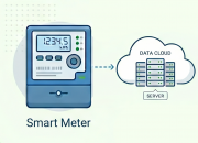
MQTT DETAILS - LKM
MQTT Publisher can be enabled and can be used in parallel with Modbus conversion (or stand alone)
MQTT Connection
Broker IP and Port can be entered
Client ID , User name and Password can be set
Publish Topic and Subscribe Topic can be defined from web interface
Data Send Interval
User can send Data send interval in seconds
Default is 60 seconds and LKM will send meter data to MQTT server in that interval
NTP Server
NTP server time will be added to each MQTT message
Data Format
There are 2 predefined formats
OBIS Values As Objects: Sends OBIS values and then mapped values in ASCII readable format
OBIS Values as Modbus Frame: Send just like the response of Modbus query as hex data (smaller data size)
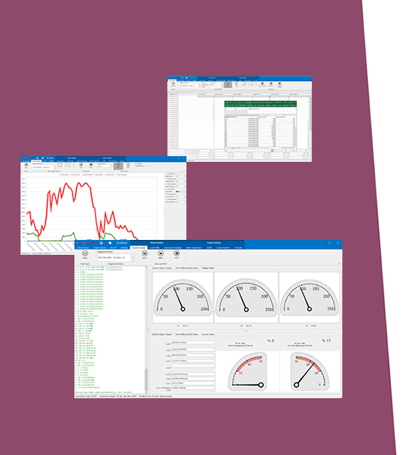
WEB MONITORING DETAILS - LKM
Meter Communication Status
User can see reading status of each meter in reading list
Last Query Time and Last Serial Package also available in this list and the meter's name/serial and protocol (IEC 62056-21 / DLMS/COSEM) are also shown.
Modbus Communication Status
User can see reading status of each Modbus client connected
Last Query Time and Last Received and Sent Packages also available in this list
Meter Reading to Modbus Mapping (Gateway) Status
User can see modbus mapping status of each meter in reading list
Data can be checked in realtime or status can be set for any specific meter in list
Ex: Show mapping status of Meter Number 2 in meter reading list only
Meter Reading Status
User can see meter reading details in real time
This data can help to select desired OBIS codes
WEB MONITORING DETAILS - LKM LoRaWAN
LoRaWAN Status
User can see LoRaWAN Network Status (Joining or Active)
LoRaWAN Tx and Rx Messages
Latest sent data package details
Number of LoRaWAN Messages sent, pending and lost
Duty Cycle Block Time
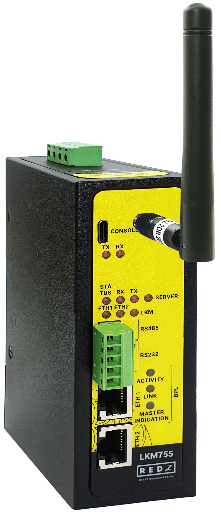
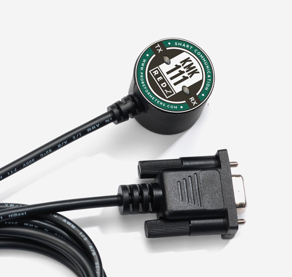
CONNECTORS AND PORTS - LoRa
SMA Antenna Connector for LoRa
1 Standard SMA female interface, 50 ohm
Console Port
USB Type C or Micro USB connection for LOG in 115200 baud
10/100T(X) RJ45 Ports
Ethernet Connection on 2 ports
Serial Ports
5 pin wired Terminal Connection
Tx, Rx, GND for RS232
A, B and GND for RS485
Reset Buttons
Reset to Client and Reset to Server Operating modes buttons
LED INDICATORS
Power Indicator
Power LED
10/100T(X) Indicators
Activity LEDs:
ETH1, ETH2 and Activity of device itself (Marked as device series name, such as CKL/TLM/HUR/LKM)
System Indicators
Status LED,
Tx and Rx of data LEDs and Server LED
Console Indicators
Tx and Rx of data LEDs
LED INDICATORS - BPL
BPL LEDs
-BPL Activity
-BPL Link
-Master Indication (LED ON: Master, LED OFF: Slave)
POWER - BPL
Power Connection
Powering up device is only done over Terminal pins 1 and 2.
Can be purchased in 2 versions:
1. AC Powered version: Device can be powered up with AC input, this option is available in both PN and PP models. It accepts, 110V–240V/50-60Hz. (Power Input can also be used for data transmission in PN Models.)
2. DC Powered version: Device can be powered up with 9-36V DC power. Data transmission only done through terminal pins 3 and 4. This model can be used if DC power source will be used in the field and available with PP or DC model.
Data Connection
Can be purchased in 3 versions:
1. PP Model: Phase to phase model (Standard Model).
Data transmission is only done through terminal pins 3 and 4. AC Phase to phase connection should be done to data transmission pins for better performance. If phase to phase connection is not available then phase and neutral can still be connected for data transmission over terminal pins 3 and 4.
(Ex: L1-L2, L2-L3, L1-L3 or L1-2-3 to N can be used as data connection)
2. PN Model: Phase to neutral model. That version gets power from terminal pins 1 and 2 from phase and neutral and it can also transmit data from that pins (pins 1 and 2). Remaining (pins 3 and 4) pins usage is optional.
(Ex: Master can be connected to all phases and slaves can be connected to relevant phases)
(Ex: L1-N, L2-N, L3-N or L1-2-3 and N can be used as data connection)
3. DC Model: DC data line model. Uses DC Power Line for data transmission. (Ex: 24V+ and GND as data connection)
PHYSICAL AND ENVIRONMENTAL CHARACTERISTICS - DC POWERED AND BPL MODELS
Enclosure
Metal, IP40
Dimensions
43 x 95 x 124 (w x d x h) mm
Weight
~400gr
Storage Temperature
-65 to 150 °C
Operating Temperature
-40 to 85 °C
Operating Humidity
5% to 95% Non-condensing
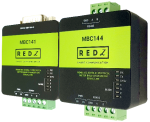
LKM755: 868MHz LoRaWAN Meter Reader and Electricity Meter Protocol to Modbus Protocol Gateway with MQTT, 2x 10/100 T(x) ETH ports + 1 x BPL (Broadband Power Line) Link, 1 x RS232 & 1 x RS485, 3 Phase AC Power Input, 110V–240V/50-60Hz