Various types of cookies are used on our website (and on all other digital platforms including mobile applications). View our new THE INFORMATIVE TEXT ON LPPD AND PRIVACY here. Google Analytics Analytical cookies help us to improve our website by collecting and reporting information on its usage. Google AdWords ve Remarketing We use marketing cookies to help us improve the relevancy of advertising campaigns you receive.
I have read the above articles
 INDEX
INDEX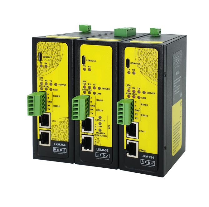
The LKM Series Electricity Meter Protocol to Modbus Protocol Gateways can read up to 32 electricity meters using both IEC 62056-21 (Mode C) and DLMS/COSEM protocols, and convert their data to Modbus registers so that field devices or remote applications can get meter data via Modbus TCP. Meter data can also be sent to an MQTT Server simultaneously. OBIS codes of the meters read are fully definable by the end user.
REDZ Broadband Power Line (BPL) link option allows device to communicate with full transparent TCP/IP standard over Low Voltage power lines and allows easy connection between TCP/IP based terminals without use of extra cables.
Typical applications: Automated Meter reading, Telemetry, Energy Management…
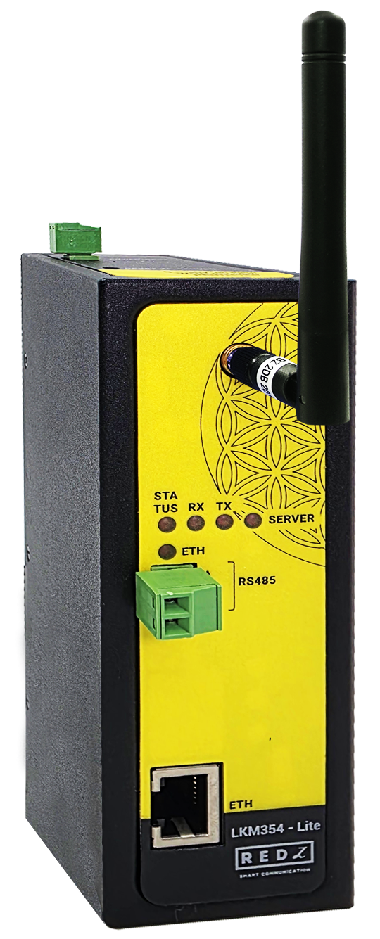
LKM Lite Models are cost effective solution for Electricity Meter Protocol to Modbus Protocol Gateway with MQTT needs.
LKM - Lite model has hardware and functional differences than normal models which can be seen from datasheet or comparison tables.
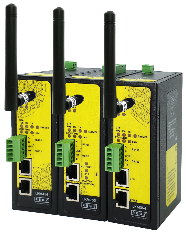
The LKM Series 868 MHz LoRaWAN Meter Reader and Electricity Meter Protocol to Modbus Protocol Gateways with MQTT can read up to 32 electricity meters using both IEC 62056-21 (Mode C) and DLMS/COSEM protocols and convert their data to Modbus registers so that field devices or remote applications can get meter data via Modbus TCP. Meter data is sent to a LoRaWAN Server through a LoRaWAN Gateway in user-defined periods. Meter data can also be sent to an MQTT Server simultaneously. OBIS codes of the meters read are fully definable by the end user.
REDZ Broadband Power Line (BPL) link option allows device to communicate with full transparent TCP/IP standard over Low Voltage power lines and allows easy connection between TCP/IP based terminals without use of extra cables.
Typical applications: Automated Meter reading, Telemetry, Energy Management…
LKM Lite Models are cost effective solution for 868MHz LoRaWAN Meter Reader and Electricity Meter Protocol to Modbus Protocol Gateway with MQTT needs.
LKM - Lite model has hardware and functional differences than normal models which can be seen from datasheet or comparison tables.
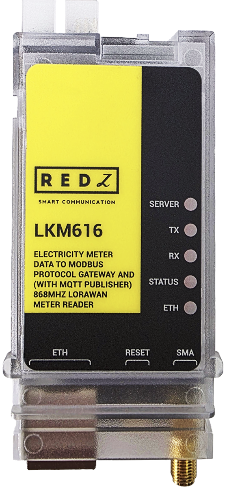
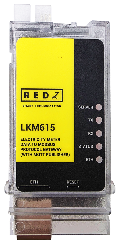
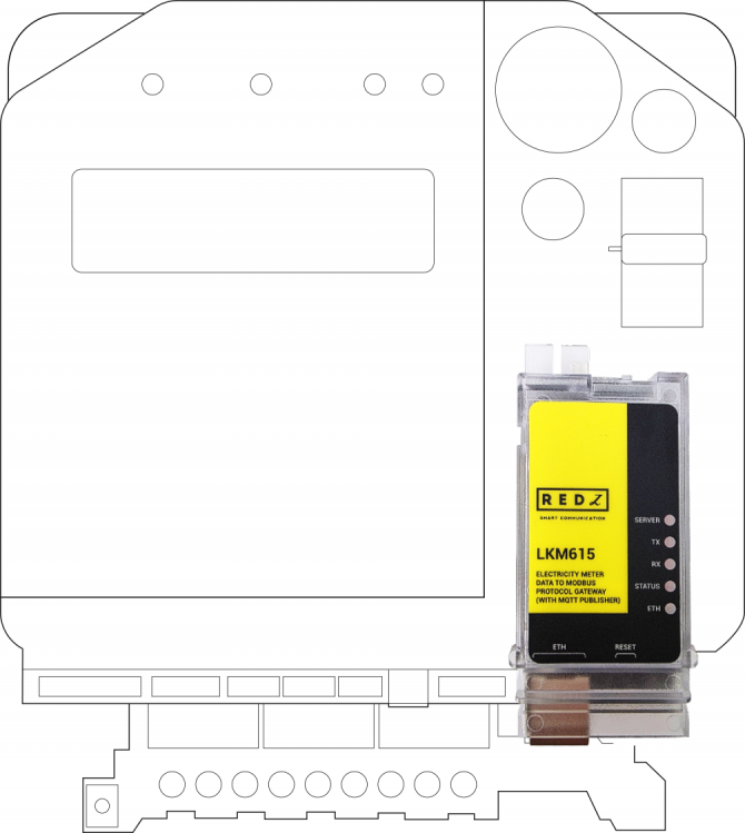
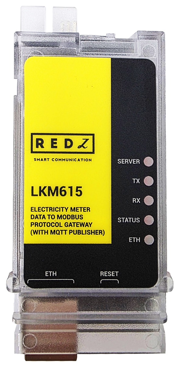
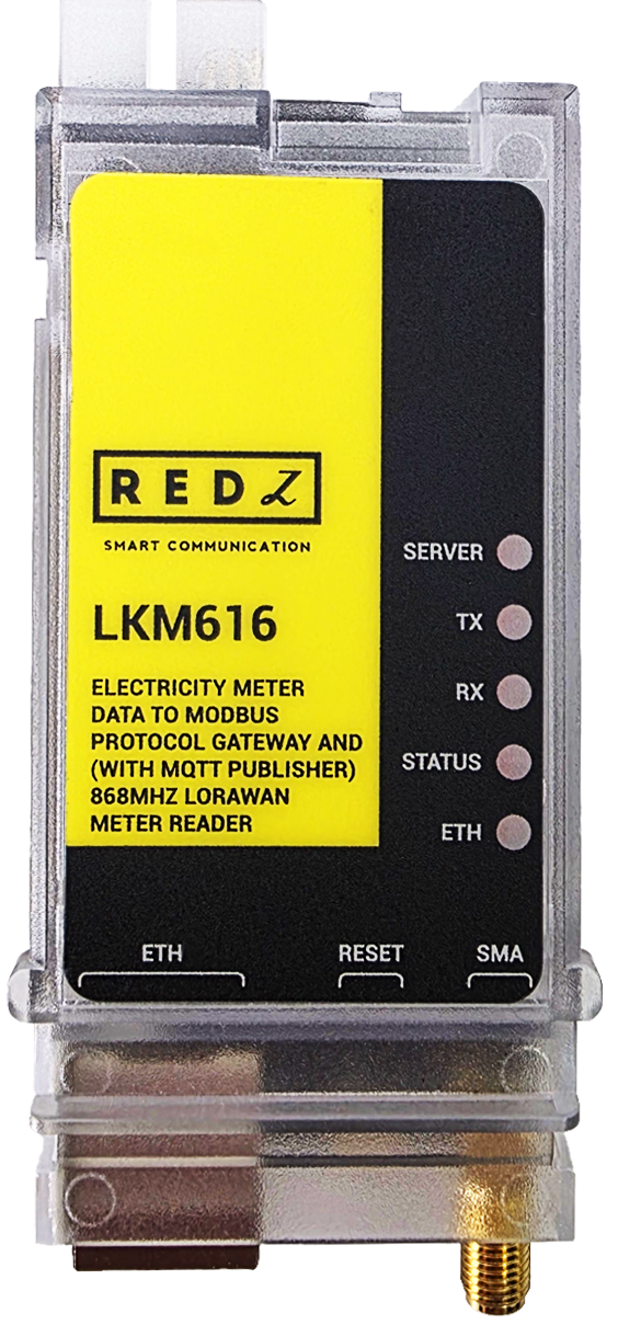
LKM615 and LKM616 are especially designed for EMH LZQJ-XC meters and are direct replacements for Variomod XC modules. They can read EMH LZQJ-XC meters using both IEC 62056-21 (Mode C) and DLMS/COSEM protocols, convert the read data to Modbus TCP and send it to an MQTT Server. LKM616 also sends meter data to a LoRaWAN Server through a LoRaWAN Gateway in user-defined periods.
LKM Series Electricity Meter Protocol to Modbus Protocol Gateways with MQTT have the versions with and without BPL (Broadband Power Line) Link.
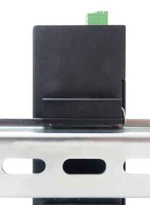
Each device has a Din-Rail kit on rear panel. The Din-Rail kit helps device to fix on the Din-Rail. Slant the switch and mount the metal spring to Din-Rail.
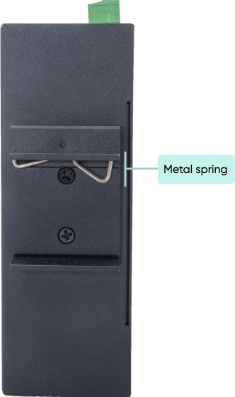
Then Push the switch toward the Din-Rail until you heard a “click” sound.
Direct Connection to Meter Models can directly fit into EMH LZQJ-XC meter. It is direct replacement for Variomod XC modules. Simply plug in LKM615 or LKM616 into meter.
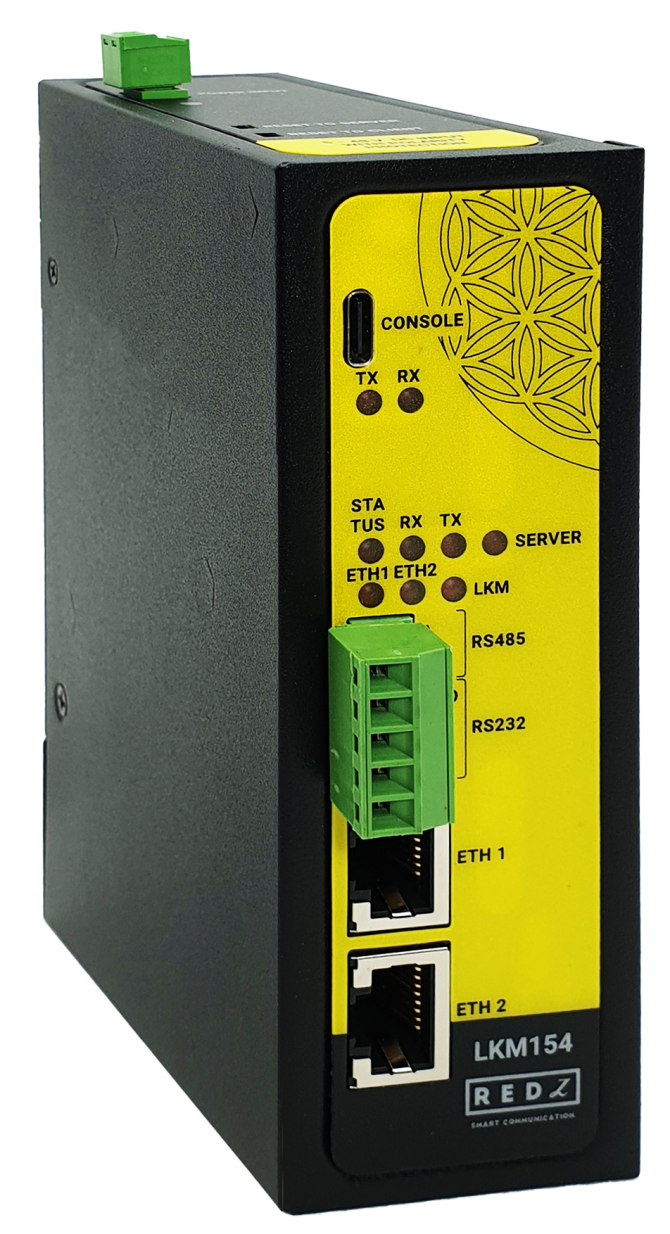
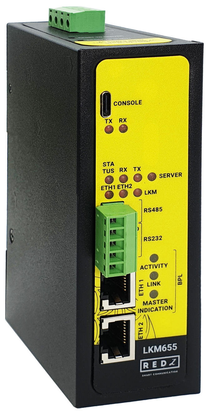
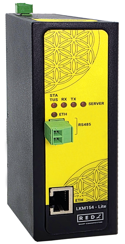
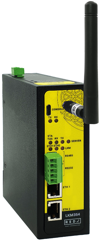
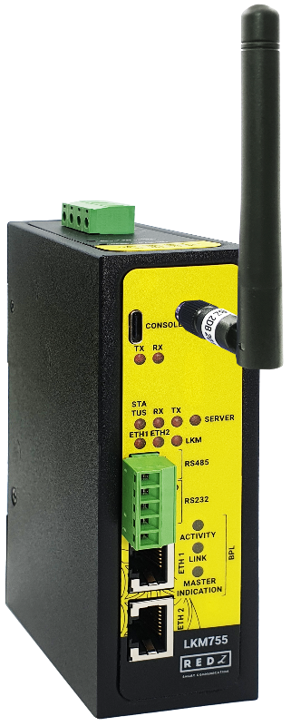
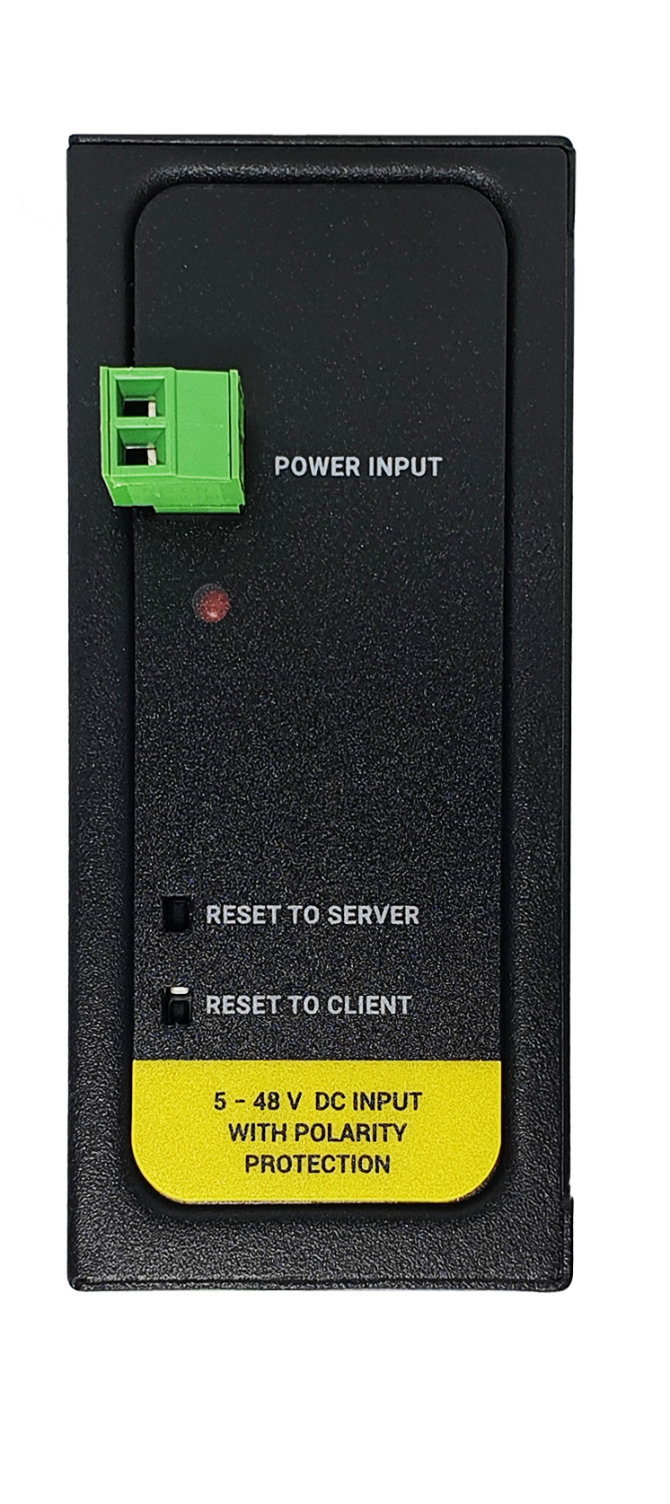
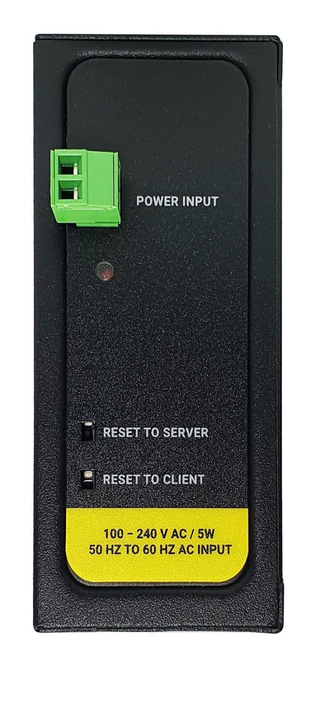
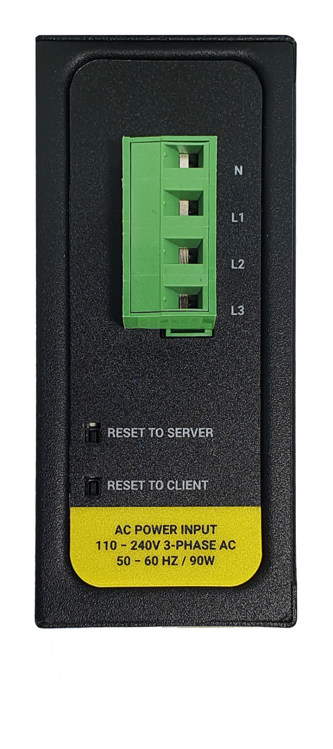
Power Input Options:
AC Power Input 110V–240V/50-60Hz
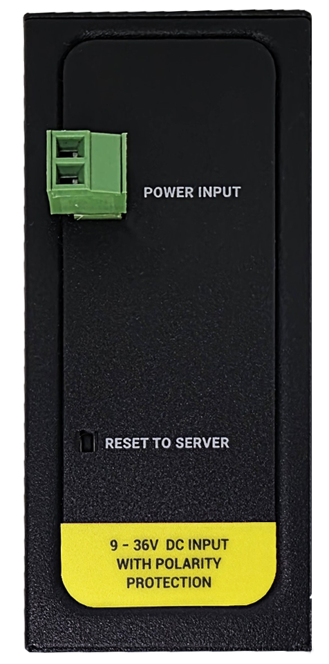
9-36V DC Power Input
Data Connectivity Options:
Phase to Phase AC Power Line
Phase to Neutral AC Power Line
DC Power Line

NOTE :
Power Connection
Powering up device is only done over Terminal pins 1 and 2.
Can be purchased in 2 versions:
1. AC Powered version: Device can be powered up with AC input, this option is available in both PN and PP models. It accepts, 110V–240V/50-60Hz. (Power Input can also be used for data transmission in PN Models.)
2. DC Powered version: Device can be powered up with 9-36V DC power. Data transmission only done through terminal pins 3 and 4. This model can be used if DC power source will be used in the field and available with PP or DC model.
Data Connection
Can be purchased in 3 versions:
1. PP Model: Phase to phase model (Standard Model).
Data transmission is only done through terminal pins 3 and 4. AC Phase to phase connection should be done to data transmission pins for better performance. If phase to phase connection is not available then phase and neutral can still be connected for data transmission over terminal pins 3 and 4.
(Ex: L1-L2, L2-L3, L1-L3 or L1-2-3 to N can be used as data connection)
2. PN Model: Phase to neutral model. That version gets power from terminal pins 1 and 2 from phase and neutral and it can also transmit data from that pins (pins 1 and 2). Remaining (pins 3 and 4) pins usage is optional.
(Ex: Master can be connected to all phases and slaves can be connected to relevant phases)
(Ex: L1-N, L2-N, L3-N or L1-2-3 and N can be used as data connection)
3. DC Model: DC data line model. Uses DC Power Line for data transmission. (Ex: 24V+ and GND as data connection)
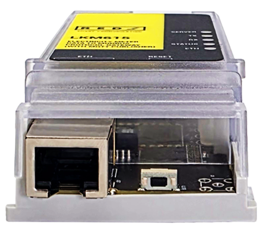
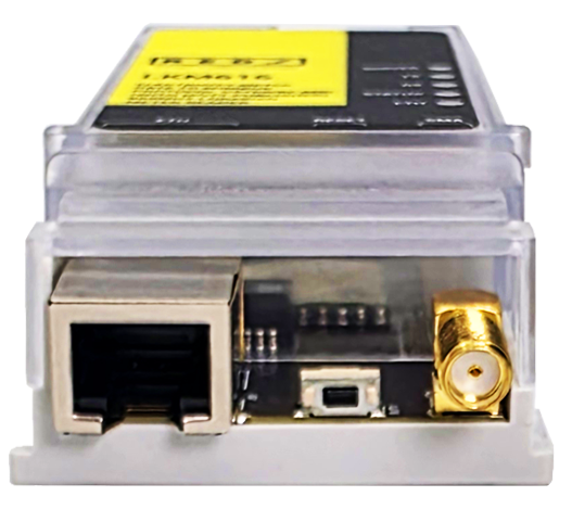
LKM Series Electricity Meter Protocol to Modbus Protocol Gateways with MQTT have standard Ethernet ports. According to the link type, the switches use CAT 3, 4, 5, 5e UTP cables to connect to any other network device (PCs, servers, switches, routers, or hubs).
| Cable | Type | Max. Length | Connector |
| 10BASE-T | Cat. 3, 4, 5 100-ohm | UTP 100 m (328 ft) | RJ-45 |
| 100BASE-TX | Cat. 5 100-ohm UTP | UTP 100 m (328 ft) | RJ-45 |
With 100BASE-TX/10BASE-T cable, pins 1 and 2 are used for transmitting data and pins 3 and 6 are used for receiving data.
| Pin Number | Description |
| 1 | TD+ |
| 2 | TD- |
| 3 | RD+ |
| 4 | Not Used |
| 5 | Not Used |
| 6 | RD- |
| 7 | Not Used |
| 8 | Not Used |
| CAT5 Based System | BPL Link Based System | |
| Media | CAT5 | Power Line |
| Bandwidth | 100Mbps | Up to 30Mbps |
| Re-Wire | Yes | No, Using existing Power Line |
| Span | <100m | <600m |
| Multiple Nodes | N/A | Up to 10 hops/1000 nodes |
| Encryption | Yes, but difficult to configure | Yes, Plug & Play |
| Installation | Difficult | Easy, simply uses existing power line |
| Installation Cost | High | Low |
| Total Cost | High | Low |
NOTE :
Power Connection
Powering up device is only done over Terminal pins 1 and 2.
Can be purchased in 2 versions:
1. AC Powered version: Device can be powered up with AC input, this option is available in both PN and PP models. It accepts, 110V–240V/50-60Hz. (Power Input can also be used for data transmission in PN Models.)
2. DC Powered version: Device can be powered up with 9-36V DC power. Data transmission only done through terminal pins 3 and 4. This model can be used if DC power source will be used in the field and available with PP or DC model.
Data Connection
Can be purchased in 3 versions:
1. PP Model: Phase to phase model (Standard Model).
Data transmission is only done through terminal pins 3 and 4. AC Phase to phase connection should be done to data transmission pins for better performance. If phase to phase connection is not available then phase and neutral can still be connected for data transmission over terminal pins 3 and 4.
(Ex: L1-L2, L2-L3, L1-L3 or L1-2-3 to N can be used as data connection)
2. PN Model: Phase to neutral model. That version gets power from terminal pins 1 and 2 from phase and neutral and it can also transmit data from that pins (pins 1 and 2). Remaining (pins 3 and 4) pins usage is optional.
(Ex: Master can be connected to all phases and slaves can be connected to relevant phases)
(Ex: L1-N, L2-N, L3-N or L1-2-3 and N can be used as data connection)
3. DC Model: DC data line model. Uses DC Power Line for data transmission. (Ex: 24V+ and GND as data connection)
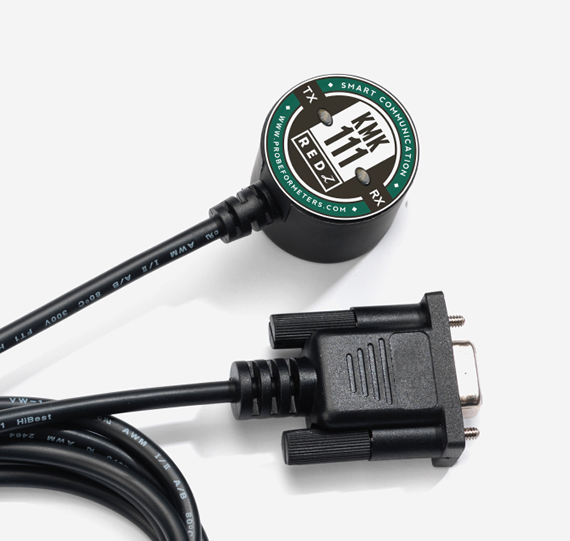
LKM Series Electricity Meter Protocol to Modbus Protocol Gateways with MQTT have 1 x RS232 and 1 x RS485 port . The serial line can be connected to electricity meters directly or over a REDZ KMK114 RS485 Optical Probe. Both IEC 62056-21 (Mode C) and DLMS/COSEM meters are supported.
NOTE: Lite Models have only 1 x RS485 serial port.
Direct Connected to Meter Models have no RS232 or RS485 port at all.
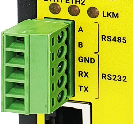
1. Terminal connector for 3 wire Tx-Rx-GND RS232 data transmission
| Pin Number | Description |
| 1 | GND |
| 2 | Rx |
| 3 | Tx |
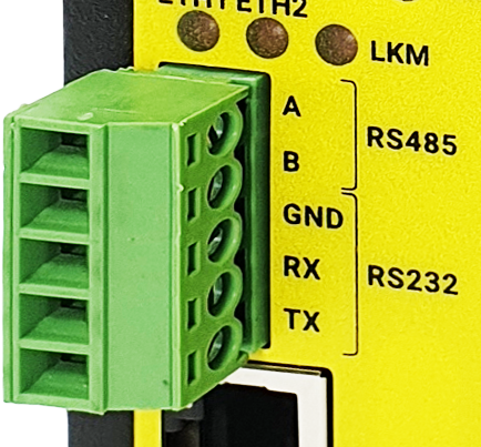
1. Terminal Connector for 2 wire RS485 connection and GND (if needed)
| Pin Number | Description |
| 1 | A |
| 2 | B |
| 3 | GND (Suggested to use) |
LKM Series Electricity Meter Protocol to Modbus Protocol Gateways with MQTT can be used in different scenarios. Usages are not limited to that examples and user may create their own usage scenario.
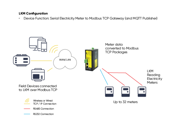
LKM Series Electricity Meter Protocol to Modbus Protocol Gateways with MQTT support up to 32 meters reading on RS485 Bus and RS232 and converts up to 48 OBIS codes to Modbus registers for each meter in reading list.
LKM Series 868MHz LoRaWAN Meter Reader and Electricity Meter Protocol to Modbus Protocol Gateways with MQTT versions can also send meter data to LoRaWAN Server.
NOTE: Lite models read up to 10 meters and only support RS485 serial connection.
Direct Connected to Meter Models can read the meter it is connected only.
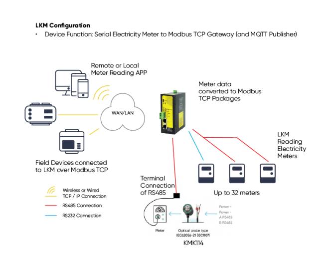
LKM Series Electricity Meter Protocol to Modbus Protocol Gateways with MQTT can be connected to RS485 or RS232 of meter and read IEC 62056-21 (Mode C) and DLMS/COSEM protocols. Remote or local Data Acquisition Server can read meter data via Modbus TCP.
LKM Series Electricity Meter Protocol to Modbus Protocol Gateways with MQTT can be connected to optical interface of meter and read IEC 62056-21 (Mode C) and DLMS/COSEM protocols, with automatic baud rate change during the IEC 62056-21 opening (applies to Mode C and to DLMS/COSEM with IEC opening). Remote or local Data Acquisition Server can read meter data via Modbus TCP.
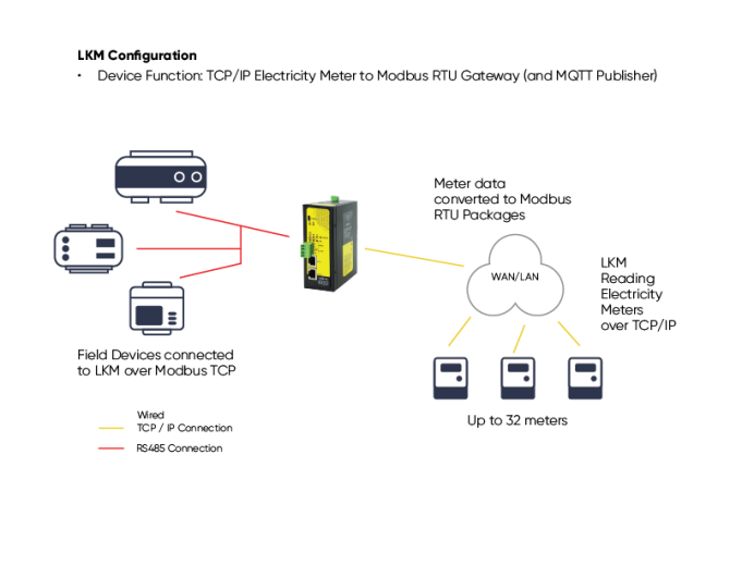
LKM Series Electricity Meter Protocol to Modbus Protocol Gateways with MQTT can also be connected to TCP/IP meters and read IEC 62056-21 (Mode C) and DLMS/COSEM protocols. Remote or local Data Acquisition Servers or field devices can read meter data via Modbus RTU in this case over serial lines.
LKM Series Electricity Meter Protocol to Modbus Protocol Gateways with MQTT can be connected to energy meters and read IEC 62056-21 (Mode C) and DLMS/COSEM protocols. All read data can be sent to MQTT server for web based applications.
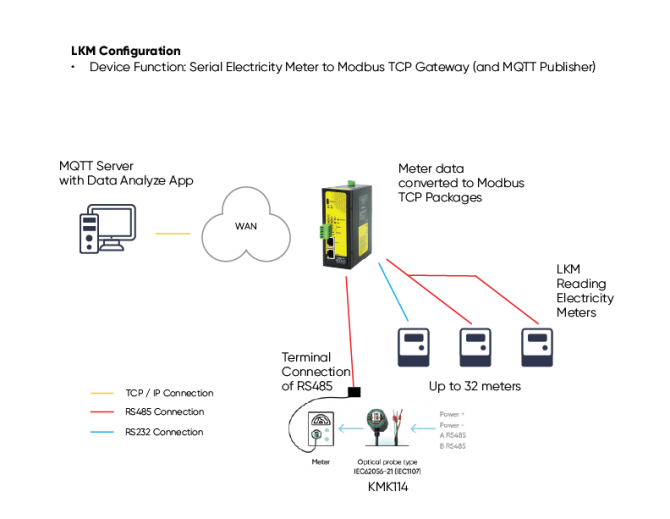
NOTE: LKM can read energy meters, convert their data to Modbus TCP and send their data to MQTT Server simultaneously.
Thus, same LKM can be used for reading meter data over Modbus TCP and sending meter data to an MQTT Server.
LKM Series 868MHz LoRaWAN Meter Reader and Electricity Meter Protocol to Modbus Protocol Gateways with MQTT can be connected to energy meters and read IEC 62056-21 (Mode C) and DLMS/COSEM protocols. All read data can be sent to LoRaWAN server for web based applications through a LoRaWAN Gateway.
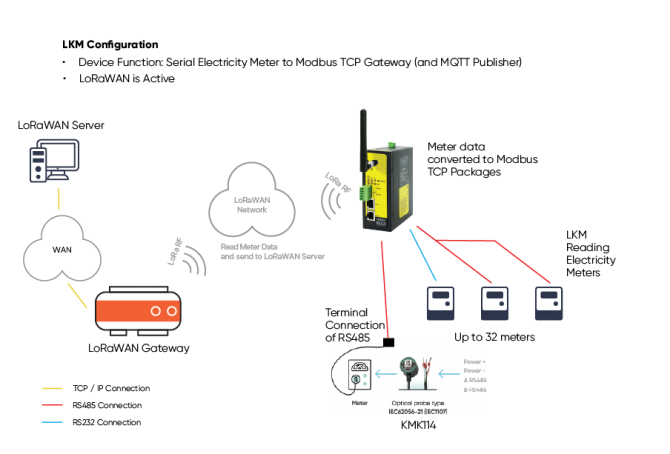
NOTE: Sending data to LoRaWAN applies only for LoRaWAN Meter Reader models.
LKM can read energy meters, convert their data to Modbus TCP and send their data to MQTT Server and send data to LoRaWAN Server simultaneously.
Thus, same LKM can be used for reading meter data over Modbus TCP and sending meter data to an MQTT Server and sending data to LoRaWAN Server.
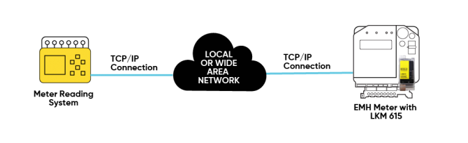
LKM615 is especially designed for EMH LZQJ-XC meters and it is direct replacement for Variomod XC modules. LKM615 can read EMH LZQJ-XC meters, convert read data to Modbus TCP and send data to MQTT Server.
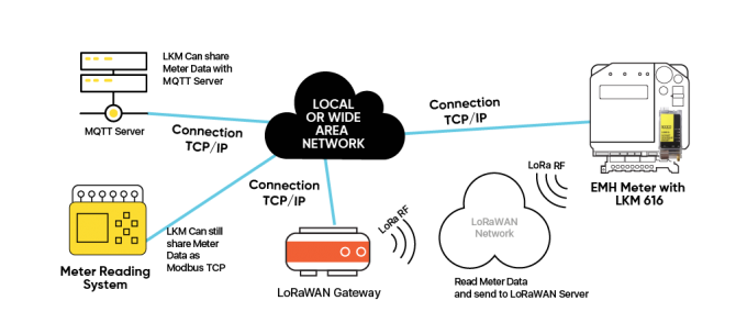
LKM616 is especially designed for EMH LZQJ-XC meters and it is direct replacement for Variomod XC modules. LKM616 can read EMH LZQJ-XC meters, convert read data to Modbus TCP and send data to LoRaWAN Server as well as MQTT Server.
LKM Series Electricity Meter Protocol to Modbus Protocol Gateways with MQTT can be configured over web interface.
Device will get IP from DHCP client when connected to a network. User can use discovery tool to see IP of the device.
Once the IP of the device is set, user may login the device by simply typing the Ip address of device.
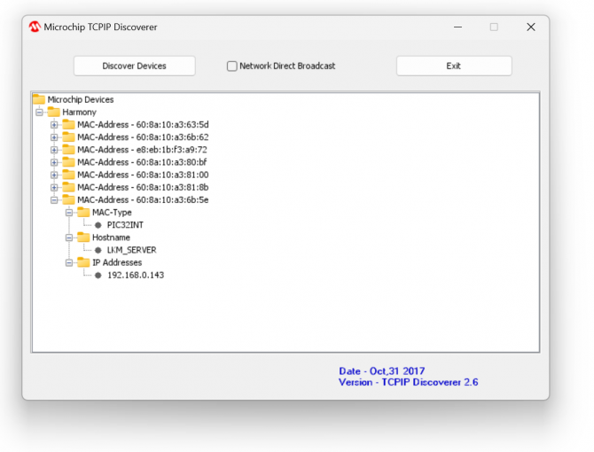
NOTE 1: LKM default firmware runs with DHCP off and expects an IP lease. If user needs static IP or prefers DHCP on during start up, it can easily be configured from the the web interface.
NOTE 2: If there is no DHCP server in LAN, REDZ device will get default 192.168.1.1 IP.
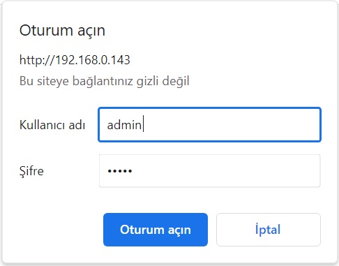
Simply write IP of the device to the http client. Login screen will pop up.
Default user name: admin
Default password: admin
Main screen of device will appear with following information:
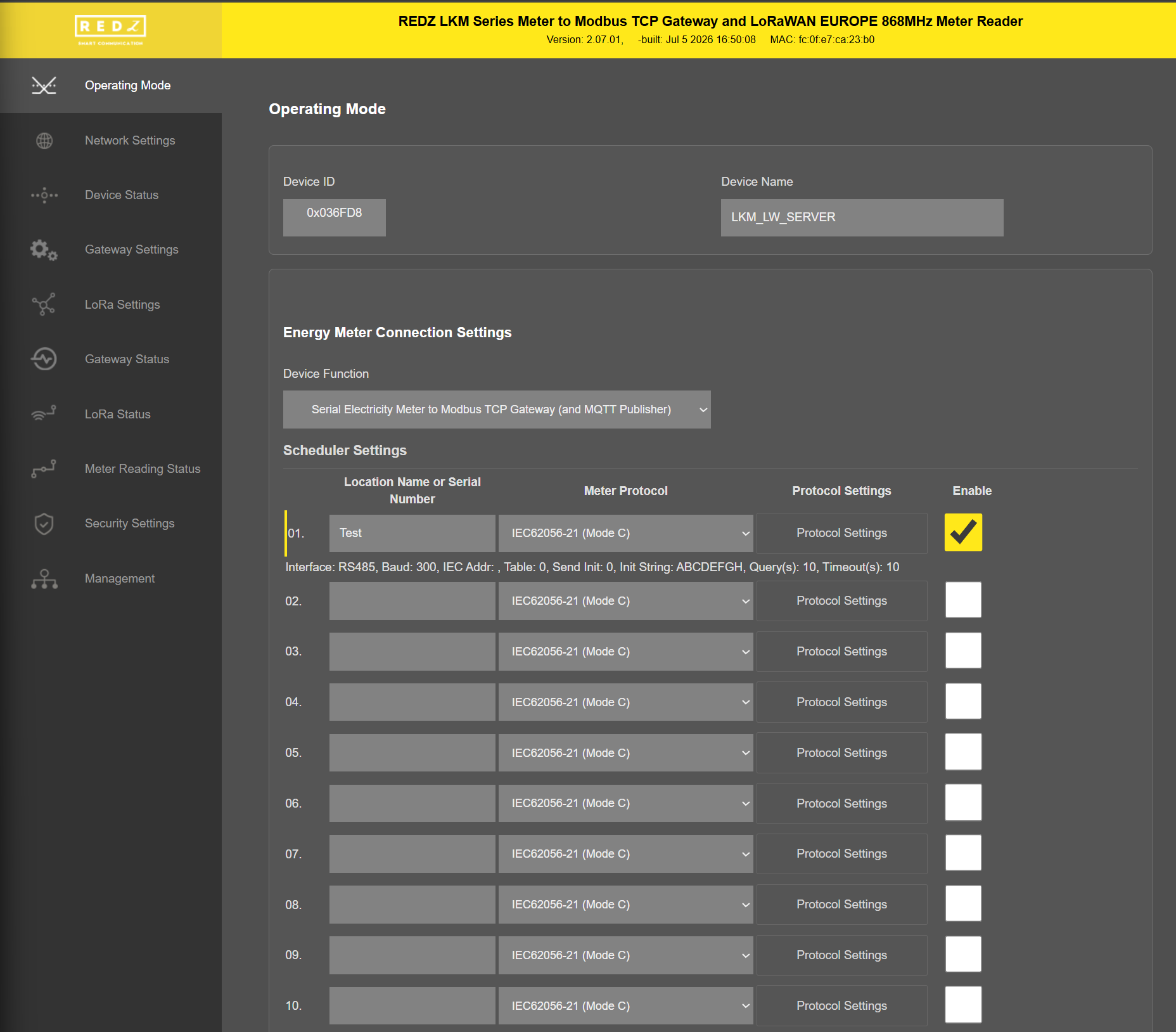
Firmware Info, MAC details and Device Name on top
Menu Items on left
Menu Item details in center
From this menu user may select the funciton of the device and enter meter reading details.
There are 2 different Device Functions:
Serial Electricity Meter to Modbus TCP Gateway with MQTT Publisher
TCP/IP Electricity Meter to Modbus RTU Gateway with MQTT Publisher
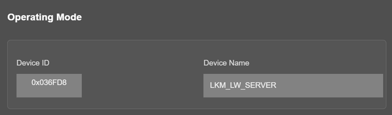
“Device Name” field is used to identify device.
When "Device Function" is set to "Serial Electricity Meter to Modbus TCP Gateway with MQTT Publisher", Scheduler Settings part will show a list to enter details regarding meter reading
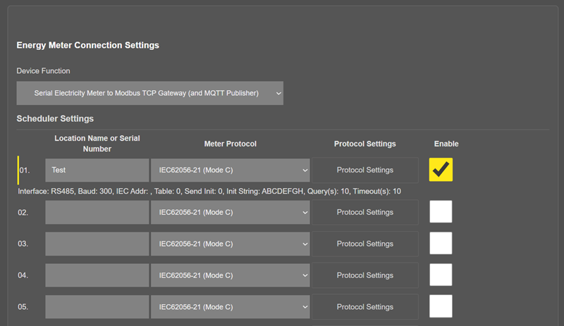
There are up to 32 rows in this list, means LKM can read up to 32 meters.
NOTE: Lite models read up to 10 meters and only support RS485 serial connection.
Direct Connected to Meter Models can read the meter it is connected only.
In the Scheduler Settings list, each meter is added as a row with the following columns: "Location Name or Serial Number" to identify the meter, "Meter Protocol" to select the reading protocol, "Protocol Settings" to open the parameter window of the meter, and "Enable" to add the meter to the reading queue.
"Meter Protocol" : Selects how the meter is read. "IEC62056-21 (Mode C)" reads the meter using the IEC 62056-21 Mode C ASCII protocol. "DLMS/COSEM" reads the meter using the DLMS/COSEM protocol. "DLMS/COSEM with IEC62056-21 Opening" reads the meter using DLMS/COSEM after starting communication with an IEC 62056-21 opening sequence.
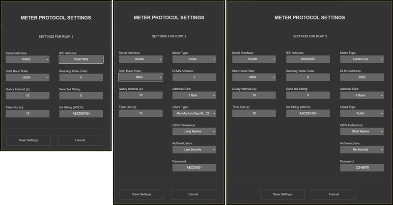
"Protocol Settings" : Opens the "Meter Protocol Settings" window, where the connection and protocol parameters of the selected meter are entered. The fields shown in this window change according to the selected Meter Protocol.
"Serial Interface": Select serial interface from which the meter be connected to LKM.
"Start Baud Rate": IEC 62056-21 Mode C Communication start baud rate should be selected. LKM will switch over target baud rate automatically based on meter response.
"Query Interval (In Seconds)": Minimum time interval to read the defined meter. LKM can read meter only after reading the other meters in defined list. So reading interval may change based on actual meter quantity in RS485 bus and data available in read out list of meter in query.
"Time Out (In Seconds)": Maximum time to wait until meter responses to initial request message.
"IEC Address": IEC 62056-21 Mode C Communication meter address. Must be entered if there are more than 1 meters on RS485 bus, otherwise the data can mix between meters.
"Reading Table Code": IEC 62056-21 Mode C Communication request message contains information regarding read out table. User can change this table number to read other tables such as Service Table.
"Send Init String": This is option to send initial string to send meter before IEC 62056-21 Mode C Communication. This is usually used to "wake up" meter. This number indicates how many times the initial string will be sent to meter.
"Init String (in ASCII)": Maximum 16 character long, initializationstring in ASCII notation. Device will add <CR> and <LF> characters at end of this string automatically. String can be letters, numbers and characters '/', '.'.
The following parameters are available when the Meter Protocol is "DLMS/COSEM" or "DLMS/COSEM with IEC62056-21 Opening":
"Meter Type" : Selects the DLMS profile of the meter. Available options are Standard DLMS, Itron, Landis+Gyr, Iskra and Cewe.
"DLMS Address" : Server (meter) address used in DLMS/COSEM communication.
"Address Size" : Length of the DLMS address; 1 Byte, 2 Bytes or 4 Bytes.
"Client Type" : DLMS client association used to connect to the meter. Available options are Management, DataCollection, Electricity, End Customer, Public and ManufacturerSpecific_32.
"OBIS Reference" : Selects how OBIS objects are referenced; Short Names or Long Names.
"Authentication" : DLMS authentication level; Low Security or No Security.
"Password" : Password used when Authentication is set to Low Security.
"Enable": Enables row and adds this details for meter reading queue.
When "Device Function" is set to "TCP/IP Electricity Meter to Modbus RTU Gateway with MQTT Publisher", Scheduler Settings will show another list to enter details regarding meter reading
There are 2 different settings here, different than "Serial Electricity Meter to Modbus TCP Gateway with MQTT Publisher"
"TCP IP Address": TCP/IP address of the meter be connected and read by LKM.
"TCP Port": TCP/IP port of the meter be connected and read by LKM.
Rest settings are same and as decribed above in "Serial Electricity Meter to Modbus TCP Gateway with MQTT Publisher" part.
When all settings done, click "Save Configuration" to save settings.
After clicking button system will tell if the settings applied successfully or not.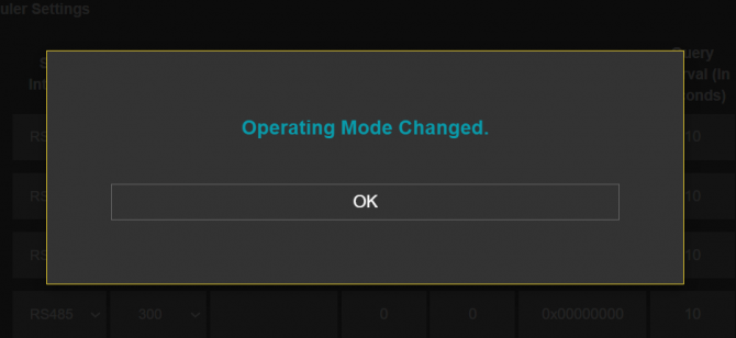
NOTE : Settings will be applied once the device is rebooted from web interface or repowered manually.
From this menu user may change the network settings of the device.
NOTE:
NTP is used to syncronize device time. Device checks if NTP time server is available in every 10 seconds after repower. Device synhcronizes its time if NTP time is available and stops checking after successfull synchronization.
In LoRaWAN versions, device synchronize time with LoRaWAN Server as well after first succesfull connection and it has higher priority than NTP time synchronization. NTP is only used to syncronize device time after a manual or system triggered restarts and it only takes place if NTP time is available and device time difference from NTP time is + or - 24 Hours.
Also following options are available when "Device Function" is set to “Serial Electricity Meter to Modbus TCP Gateway with MQTT Publisher”.
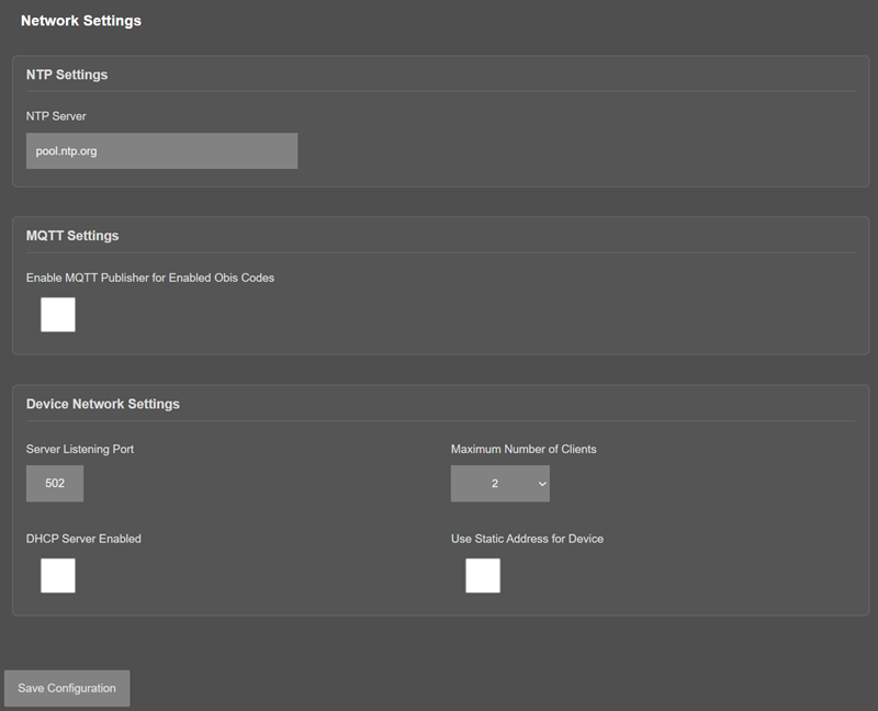
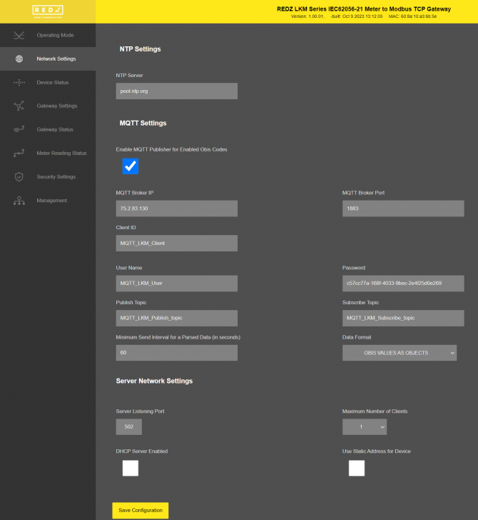
"NTP Server": NTP Server address that used in MQTT data transmission.
"Enable MQTT Publisher for Enabled Obis Codes": Click to enable MQTT Publisher. LKM will send data read from meters for enabled OBIS codes (there are up to 48 available) to MQTT Server
If "Enable MQTT Publisher for Enabled Obis Codes" is checked, following settings will be shown.
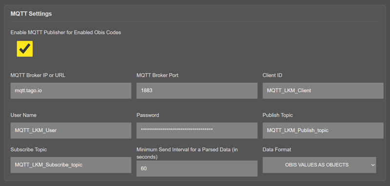
"MQTT Broker IP or URL": IP or URL of the MQTT Server. User can enter an IP address or a URL. Maximum length for this field is 64.
Ex: 75.2.83.130 is for "https://tago.io/" web address
"MQTT Broker Port": TCP Port of the MQTT Server.
Ex: 1883 is for "https://tago.io/" web address
"Client ID": MQTT Publisher client ID. Default is MQTT_LKM_Client.
Maximum length for this field is 32.
"User Name": MQTT Publisher user name. This must be entered based on MQTT server settings.
Maximum length for this field is 64.
"Password": MQTT Publisher password. This must be entered based on MQTT server settings.
Maximum length for this field is 48.
"Publish Topic": MQTT Publisher topic value. Default is MQTT_LKM_Publish_topic.
Maximum length for this field is 32.
"Subscribe Topic": MQTT Publisher subscribe topic value. Default is MQTT_LKM_Subscribe_topic.
Maximum length for this field is 32.
"Minimum Send Interval for a Parsed Data (in seconds)": Minimum value to send meter data to MQTT Server. This time may be longer due to meter quantity in reading queue.
"Data Format": Options for how data is shared by LKM with MQTT server. There are 2 options:
OBIS Values as Objects
OBIS Values as Modbus Frame
When selected as "OBIS Values as Objects", LKM will share data as follows
Device Name, Time (UTC Unix timestamp, added when NTP time is synchronized), Meter Address, Meter Number in Reading List, Data itself in pairs OBIS Code and Matched Value in ASCII readable format
Here is an example:
"F.F" OBIS code is the first one and not read, which is shown as "-"
Next is "0.9.1" OBIS code which is "165043"
Next values can be seen in same manner.
When selected as "OBIS Values as Modbus Frame", LKM will share data as follows
Device Name, Time (UTC Unix timestamp, added when NTP time is synchronized), Meter Address, Meter Number in Reading List, Data itself in hexadecimal format just like a Modbus query response. First byte will show data bytes count and rest is the data itself. For 48 OBIS Codes, there will be 192 bytes.
Here is an example:
C0 in beginning is hexadecimal equivalent for 192 data bytes count
Next is "F.F" OBIS code is not read as shown above which is "00000000"
Next is "0.9.1" OBIS code which is "0002857C" which is 165244 in decimal.
Next values can be seen in same manner.
Following parameters and static IP settings available for “Device Network Settings” part.
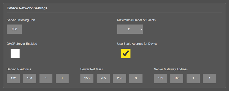
"Listening Port": TCP Port that LKM uses for incoming connections. Remote devices can use LKM IP and this port to connect to LKM for Modbus TCP query.
"Maximum Number of Clients": Maximum numbers of incoming connections accepted. LKM can accept up to 10 simultaneous connection and all devices can query Modbus TCP.
"Use Static Address for Device": Set a static TCP IP for LKM from this part. Enable and enter network settings and LKM will be available to connect from this static IP locally or remotely (gateway must be set properly for remote WAN connection).
Following parameters available if “DHCP Server” setting is enabled. This is used if DHCP server is needed in network. LKM can distribute IP to field devices connected to it in this way.
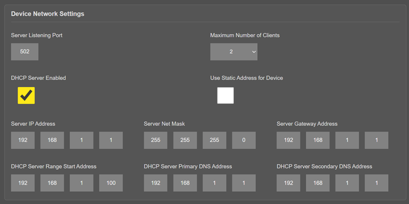
Also if the device has Broadband Power Line (BPL) option:
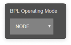
User can select operating mode of BPL either MASTER or NODE.
NOTE: Standard firmware of REDZ BPL supports up to 10 hops and 1000 nodes. Only 1 device can be MASTER in same network.
Once the setting has been changed, “Save Configuration” button will be enabled.
After clicking button system will tell if the settings applied successfully or not.
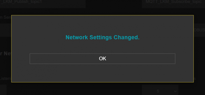
NOTE : Settings will be applied once the device is rebooted from web interface or repowered manually.
NOTE: This menu item is only available when "Device Function" is set to “TCP/IP Electricity Meter to Modbus RTU Gateway with MQTT Publisher”.
From this menu user may select RS232 or RS485 connection for Modbus RTU communication.
NOTE: Lite models only support RS485 serial connection.
Direct Connected to Meter Models have no RS232 or RS485 port at all.
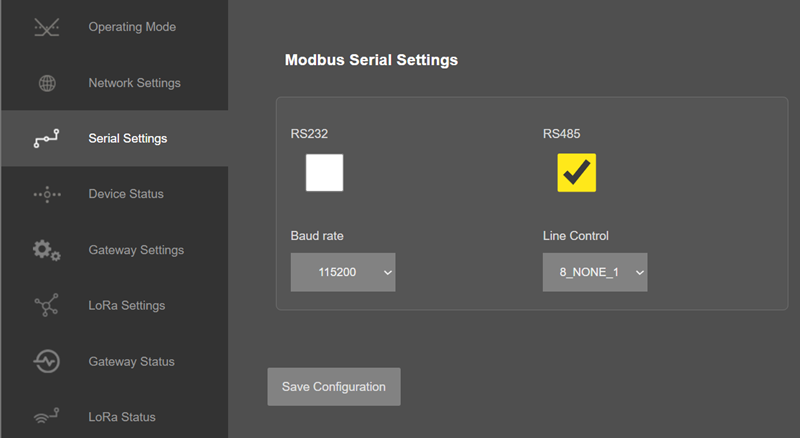
"Baud rate": Serial communication baud rate selection.
"Line Control": Serial communication data type selection in form of Data bits-Parity-Stop bits. Available options are:
8_NONE_1
9_NONE_1
8_EVEN_1
8_EVEN_2
8_ODD_1
8_ODD_2
8_NONE_2
9_NONE_2
Once the setting has been changed, “Save Configuration” button will be enabled.
After clicking button system will tell if the settings applied successfully or not.
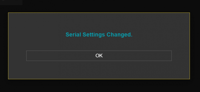
NOTE : Settings will be applied once the device is rebooted from web interface or repowered manually.
From this menu user may monitor device status and statistics based on operating mode of device. The page also helps users to check meter reading and modbus communication status.
The "Last update: hh:mm:ss" indicator shows the time the status was last read from the device; it is updated each time the page is refreshed. Only enabled meters are listed in the "Meter Communication Status" table.
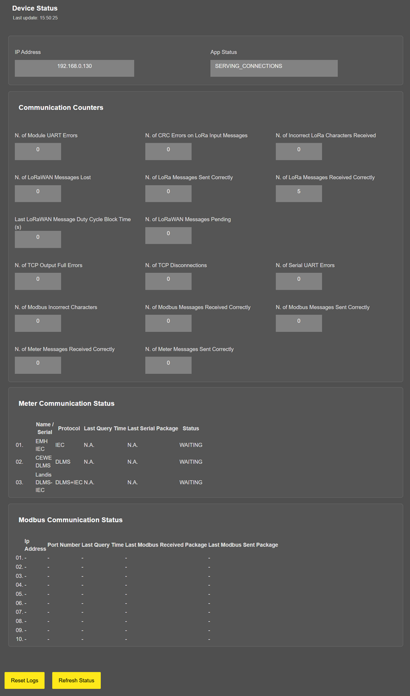
In "Device Status" part:
"IP Address": TCP/IP address of LKM itself.
"App Status": It shows current status of LKM application. "SERVING CONNECTIONS" means device is ready for normal operation.
"Log Status": It is only available when "Log" is enabled from "Management" menu and shows current status of LKM logging. "LOG_STATE_TRYWRITELOG" means normal operation.
"Log Counter": It is only available when "Log" is enabled from "Management" menu and shows how many log lines has been transfered till now.
"MQTT Sent Messages": It is only available when "MQTT" is enabled from "Network Settings" menu and shows how many MQTT messages has been transfered till now.
"MQTT Status": It is only available when "MQTT" is enabled from "Network Settings" menu and shows current status of LKM MQTT Publisher. "APP_MQTT_STATE_SUBSCRIBED" means MQTT publisher is ready for normal operation.
The counters below are listed under the "Communication Counters" section:
"N. of TCP Output Full Errors": Number of TCP output full errors during trying to send data to TCP client. Device will enter "Reboot State" if this number is above 5.
"N. of TCP Disconnections": Number of TCP disconnections from LKM.
"N. of Serial UART Errors": Number of Serial side uart errors both on RS232 and RS485.
"N. of Modbus Incorrect Characters": Number of incorrect characters received that does not accepted as valid Modbus protocol command.
"N. of Modbus Messages Received Correctly": Number of Modbus messages received by LKM.
"N. of Modbus Messages Sent Correctly": Number of Modbus messages sent by LKM.
"N. of Meter Messages Received Correctly": Number of data packages received from meters both on RS232 and RS485 lines (or TCP/IP line based on device function).
"N. of Meter Messages Sent Correctly": Number of data packages sent to meters both on RS232 and RS485 lines (or TCP/IP line based on device function).
In "Meter Communication Status" part:
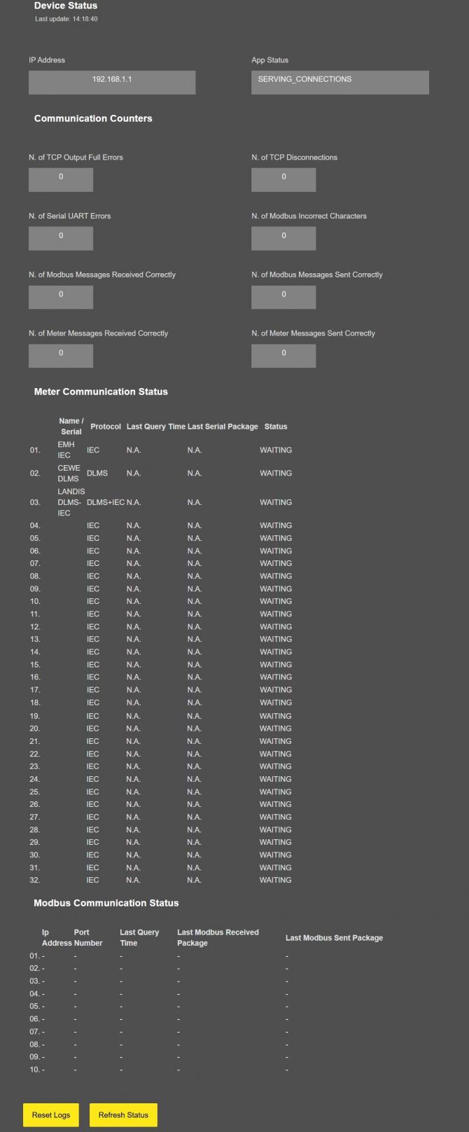
"Name / Serial" : The location name or serial number configured for the meter, shown for ease of monitoring.
"Protocol" : The communication protocol configured for the meter (IEC62056-21 (Mode C), DLMS/COSEM or DLMS/COSEM with IEC62056-21 Opening).
"Last Query Time": Is the last time this meter is tried to read. Time is shown starting from device repower/reset.
"Last Serial Package": Is the last response from this meter to request message sent by LKM.
"Status": Is the status of meter reading.
In "Modbus Communication Status" part:
"Ip Address": Is the TCP IP address of client connected to LKM.
"Port Number": Is the TCP Port number of client connected to LKM.
"Last Query Time": Is the last time this client queried LKM with a Modbus TCP message. Time is shown starting from device repower/reset.
"Last Modbus Received Package": Is the last Modbus TCP query message from this client received by LKM.
"Last Modbus Sent Package": Is the last Modbus TCP response message for this client sent by LKM.
After clicking “Refresh Status” button, system will reload data only and will not reload page. Button will be disabled during reload for an instance. If timeout occurs during the reload, the button will be enabled again with warning of timeout. In normal operation reload of status data will be done immediately. "Reset Logs" button will reset device status parameres.
NOTE 1: LKM Series 868MHz LoRaWAN Meter Reader and Electricity Meter Protocol to Modbus Protocol Gateways with MQTT have slightly different menu and will have following extra items:
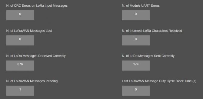
"N. of CRC Errors on LoRa Input Messages": Number of CRC errors during getting LoRa packages.
"N. of Module UART Errors": Number of module uart errors.
"N. of LoRa Messages Lost": Number of LoRaWAN messages lost (and failed to transmit to LoRaWAN Server) due to too much data in memory queue. User can try reduce data query interval from field device in that case.
"N. of Incorrect LoRa Characters Received": Number of Incorrect characters received during getting LoRa packages.
"N. of LoRa Messages Received Correctly": Number of LoRa packages received successfully over the LoRaWAN Network.
"N. of LoRa Messages Sent Correctly": Number of LoRa packages sent to LoRaWAN Network successfully.
"N. of LoRaWAN Messages Pending": Number of LoRaWAN messages pending in the memory of device.
NOTE 2: Device can store 1 message for each meter defined in device and data will not be renewed untill it is sent to LoRaWAN Server.
"Last LoRaWAN Message Duty Cycle Block Time (s)": Duty Cycle Block Time shows how much device will wait after last message sent to LoRaWAN Server due to Duty Cycle Limitations.
NOTE 3: "Modbus Communication Status" will list based on "Maximum Number of Clients" set in "Network Settings" menu.
NOTE 4: When LKM "Device Function" is set to "TCP/IP Electricity Meter to Modbus RTU Gateway with MQTT Publisher", it will have similar status menu. LKM will read remote TCP IP meters and convert data to Modbus RTU.
Thus the serial status will show data for Modbus RTU and TCP status will show data for meter in query.
From this menu user may change LKM gateway parameters.
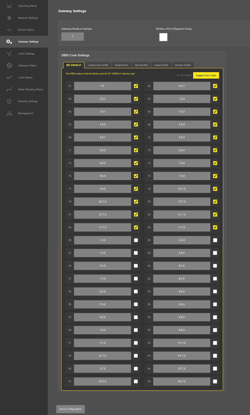
"Gateway Modbus Address": Is the Modbus address of LKM.
"Modbus Word (Register) Swap": Is the option for Modbus data format. LKM can send meter data in Modbus frame with word swap.
As an example if data is "1234 ABCD" and this option is selected, LKM will send as "ABCD 1234".
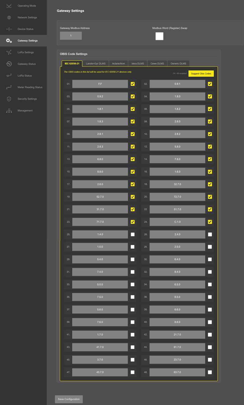
The OBIS codes are organized under the "OBIS Code Settings" section into six profile tabs, one for each meter type. Selecting a tab shows and lets the user edit the OBIS code set of that profile, in this order: "IEC 62056-21", "Landis+Gyr DLMS", "Actaris/Itron", "Iskra DLMS", "Cewe DLMS" and "Generic DLMS". The profile used for a meter is determined by the Meter Protocol and Meter Type selected for that meter in the "Operating Mode" menu. Each profile can hold up to 48 OBIS codes.
"Suggest Obis Codes" : Fills the currently selected profile with a default set of OBIS codes suitable for that meter type, which can then be adjusted one by one.
"Obis Code": OBIS code itself. User may change one by one based on read out list of meter in query.
NOTE: An easy way to change OBIS codes based on read ot list is to open 2 web pages side by side for same LKM. First will show "Gateway Settings" and second will show "Meter Reading Status", so that user can see the read out data and change OBIS code needed easily.
"Enable": If any of OBIS code is enabled, that will be searched for during meter reading and will be mapped in Mdobus registers.
After clicking “Refresh Status” button, system will reload data only and will not reload page. Button will be disabled during reload for an instance. If timeout occurs during the reload, the button will be enabled again with warning of timeout. In normal operation reload of status data will be done immediately.
Once the setting has been changed, “Save Configuration” button will be enabled.
After clicking button system will tell if the settings applied successfully or not.
NOTE: This menu is available for LoRaWAN Meter Reader Models only.
From this menu user may change LoRaWAN parameters.
LKM uses Semtech’s LoRa proprietary spread spectrum modulation technique. This modulation, in contrast to conventional modulation techniques, permits an increase in link budget and increased immunity to in-band interference. It achieves sensitivities 8 dB better than FSK modulation.
LoRa also provides significant advantages in both blocking and selectivity, solving the traditional design compromise between range, interference immunity and energy consumption.
Tx Power Level EIGRP is calculated as following:
Max. EIRP = MIN (Max. allowed EIRP, Max. RF Power + RF Gain + 2.15dB)
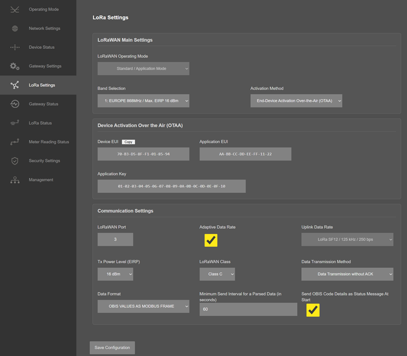
If ABP is selected, following settings will be available:
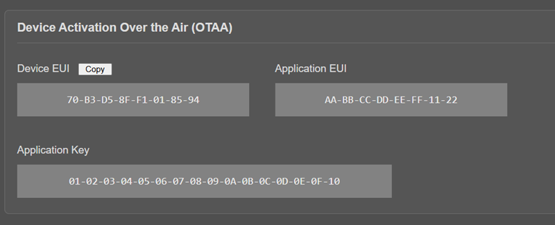
LKM Series 868MHz LoRaWAN Meter Reader and Electricity Meter Protocol to Modbus Protocol Gateways with MQTT can send data to LoRaWAN Server in user defined periods.
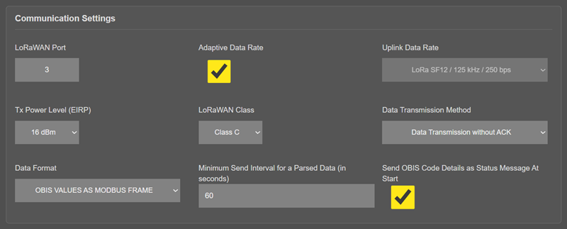
"Minimum Send Interval for a Parsed Data (in seconds)": Minimum value to send meter data to MQTT Server. This time may be longer due to meter quantity in reading queue.
"Data Format": Options for how data is shared by LKM with LoRaWAN server. There is 1 option for now:
Parsed Data as Modbus Frame
"Send OBIS Code Details as Status Message At Start": If enabled, LKM will send status message for enabled/configured OBIS codes in system to LoRaWAN Server. If not needed, it can be disabled.
The details of how data sent to LoRaWAN Server and payload formatting is described in Chapter 13 "LoRaWAN Communication Example" with example application.
NOTE 1: There are 2 Status Messages available, 1 sent in every connection to LoRaWAN Server, the other is optional.
Status Message - Device Status
Message sent to LoRaWAN Port number 1 in every connection to LoRaWAN Server
4 Bytes: LKM unique Device Id
1 Byte: Message Type (lower 4 bits) and Package Number (upper 4 bits).
0x00 : Device Status message
1 Byte: Number of Meters configured to be read
6 Bytes: Number of OBIS Codes configured to be read (one byte for each of the 6 OBIS profiles)
1 Byte: LoRaWAN Port of the response package
4 Bytes: RTC Time
3 Bytes: LKM Device firmware version
N Bytes (maximum 22): LKM Device name configured by user
Status Message - OBIS Details
Message sent to LoRaWAN Port number 1 in every connection to LoRaWAN Server if enabled by user.
4 Bytes: LKM unique Device Id
1 Byte: Message Type (lower 4 bits) and Package Number (upper 4 bits).
0x01 : OBIS Details message
OBIS records are shared one by one in the following 8-byte format (the per-profile quantity is given in the Device Status message):
1 Byte: OBIS profile index (0 to 5)
1 Byte: OBIS index within the profile (1-based)
6 Bytes: the six OBIS code groups (A, B, C, D, E and F), one byte each
....Next OBIS record, as many as the maximum payload size allows.
NOTE 2: Data sent to LoRaWAN Server only if meter data is read and minimum data send interval has passed. Here is data format:
Meter Data Message - Parsed from Meter Reading
Message sent to LoRaWAN configured Port (default is 3) and minimum send interval can be configured by user
4 Bytes: LKM unique Device Id
1 Byte: Message Type (lower 4 bits) and Package Number (upper 4 bits).
0x02: Meter Data message
1 Byte: Read Meter number in same sequence configured from web interface
1 Byte: Data Starting OBIS Code Number in same sequence configured from web interface
1 Byte: Total Data Size in Payload
Meter Data Frames are shared 1 by 1 in following format, each data is 4 bytes
4 Bytes: Meter Data (scaled 32-bit integer; word order follows the Modbus Word Swap setting)
....Next data that maximum payload size allows
Once the setting has been changed, “Save Configuration” button will be enabled.
After clicking button system will tell if the settings applied successfully or not.
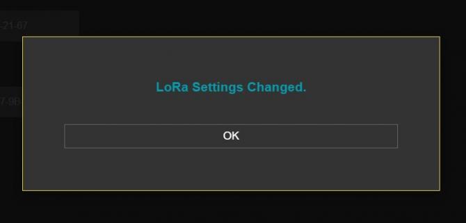
NOTE : Settings will be applied once the device is rebooted from web interface or repowered manually.
From this menu user may monitor gateway status and statistics. The page also helps users to check meter OBIS codes to Modbus registers mapping.
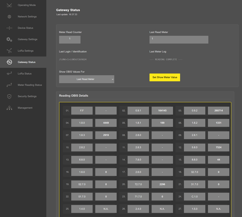
"Meter Read Counter": Number of total successfull reading of meters in list..
"Last Read Meter": The number of meter in list which is last read.
"Last Identification Message": Last Identification message received from the meter in query.
"Latest Received Message": Last data package received from the meter in query.
In "Show OBIS Values For" part:

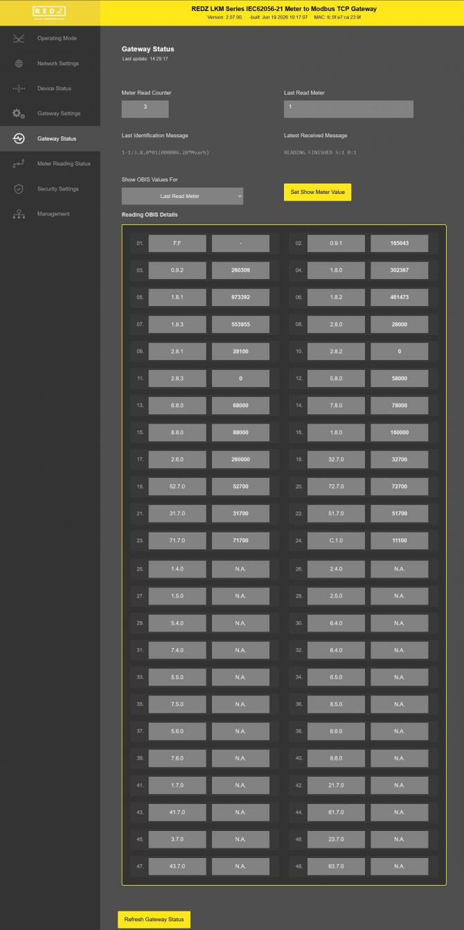
"Show OBIS Values For": Default value is "Last Read Meter". That means when user clicks "Refresh Gateway Status", LKM will show latest OBIS codes and found values for last read meter.
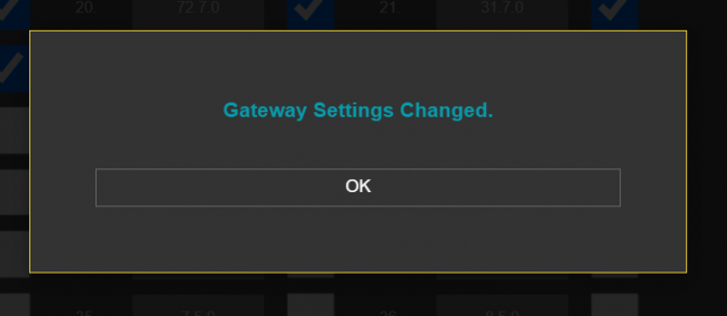
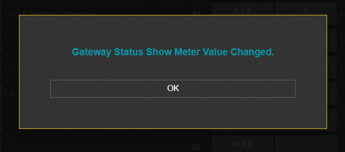
If read out values of specific meter is needed, user may select the meter number in list and click "Set Show Meter Value". LKM will confirm this change with following pop up screen.
Then, "Reading OBIS Details" part will show values for selected meter in list whenever "Refresh Gateway Status" clicked.
In "Reading OBIS Details" part:
"Obis Code": Is the configured OBIS code for look for in reading, shown for ease of monitoring.
"Found Value": Is the value found for this specific OBIS code in meter read out list.
NOTE: If OBIS code not enabled, it will show N.A.
If not found it will show "-".
After clicking “Refresh Status” button, system will reload data only and will not reload page. Button will be disabled during reload for an instance. If timeout occurs during the reload, the button will be enabled again with warning of timeout. In normal operation reload of status data will be done immediately.
Each time "Refresh Gateway Status" is pressed, the time of the update is shown as "Last update: hh:mm:ss".
From this menu user may monitor LoRa status and package details. Package from gateway side comes from either TCP/IP or RS232/RS485 serial line based on operating mode of device. The page also helps users to diagnose LoRaWAN connection status.
The page has several parts.
LoRaWAN Network/Activation Status:
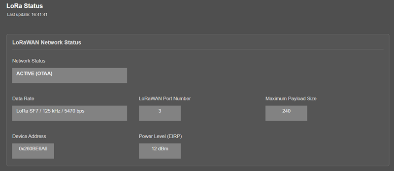
"Network Status": That part shows if the LKM is Active in LoRaWAN Network or not. Following Options are available:
Active (ABP)
Active (OTAA)
Joining (OTAA)
If the devices goes to "Active" status, the other LoRaWAN network information will be available as well.
"Data Rate": Shows current data rate used to send data packets in the next uplink.
"LoRaWAN Port Number": Shows the LoRaWAN Port Number used for sending data packets in the next uplink.
"Maximum Payload Size": Shows maximum payload size allowed in LoRaWAN Network.
"Device Address": Shows unique 32-Bit device address that is used for sending data packets in LoRaWAN Network.
"Power Level (EIRP)": Shows current configured transmit power level.
Latest Sent and Received LoRaWAN Data Message Details:
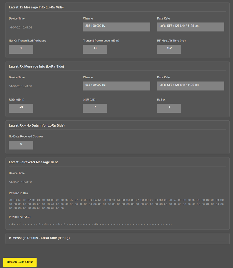
"Device Time": Shows the system time when latest LoRaWAN message sent.
"Data Rate": Shows the data rate of latest LoRaWAN message sent.
"Channel": Shows the channel of latest LoRaWAN message sent.
"Nu. Of Transmitted Packages": Shows the number of radio packages used for latest LoRaWAN message sent.
"Transmit Power Level (dBm)": Shows the transmit power level in dBm of latest LoRaWAN message sent.
"RF Msg. Air Time (ms)": Shows the airtime in miliseconds of latest LoRaWAN message sent.
"No Data Received Counter": Shows the numbe rof LoRaWAN messages received without any data.
"Device Time": Shows the system time when latest LoRaWAN message received.
"Data Rate": Shows the data rate of latest LoRaWAN message received.
"Channel": Shows the channel of latest LoRaWAN message received.
"RSSI (dBm)": Shows the RSSI value in dBm of latest LoRaWAN message received.
"SNR (dB)": Shows the SNR value in dB of latest LoRaWAN message received.
"RxSlot": Shows the Rx Slot value of latest LoRaWAN message received.
Latest LoRaWAN and Gateway Side Message Details:
Gateway side is TCP/IP or Serial side based on user settings.
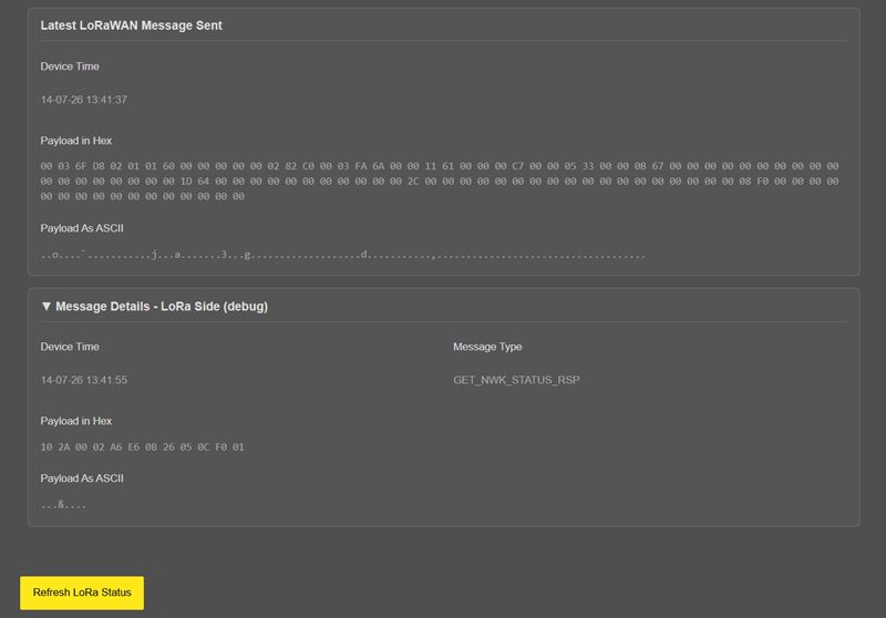
"Device Time": Shows the system time when latest LoRaWAN message received.
"Message Type": That part shows latest received LoRaWAN message type. Following Options are available:
GET_NWK_STATUS_RSP
RECV_CDATA_IND
RECV_UDATA_IND
RECV_NO_DATA_IND
SEND_CDATA_TX_IND
SEND_CDATA_RSP
SEND_UDATA_TX_IND
SEND_UDATA_RSP
JOIN_NETWORK_IND
JOIN_NETWORK_TX_IND
OTAA_JOIN_NETWORK_RSP
OTAA_SET_JOIN_PARAM_RSP
ABB_ACTIVATE_DEVICE_RSP
"Payload in Hex": Shows latest LoRaWAN message received payload in Hexadecimal format.
"Payload As ASCII": Shows latest LoRaWAN message received payload in ASCII format.
"Device Time": Shows the system time when latest Gateway side message received.
"Payload in Hex": Shows latest Gateway side message received payload in Hexadecimal format.
"Payload As ASCII": Shows latest Gateway side message received payload in ASCII format.
Each time "Refresh LoRa Status" is pressed, the time of the update is shown as "Last update: hh:mm:ss".
From this menu user may monitor instantaneous meter reading status. It is helpful to check meter reading data and OBIS code settings.
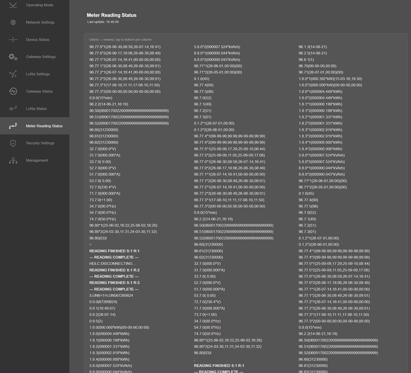
After clicking “Refresh Status” button, system will reload data only and will not reload page. Button will be disabled during reload for an instance. If timeout occurs during the reload, the button will be enabled again with warning of timeout. In normal operation reload of status data will be done immediately.
Each time "Refresh Meter Reading Status" is pressed, the time of the update is shown as "Last update: hh:mm:ss".
In the status list the reading state of each meter is colour-coded: green for a finished reading ("READING FINISHED"), amber for "READING COMPLETE", and red for a problem such as rejected, error, mismatch or no data.
NOTE: This menu item is only available when "Device Function" is set to “Serial Electricity Meter to Modbus TCP Gateway with MQTT Publisher”.
From this menu user may activate TCP IP filter based on White list (accepted packages from IP Address) or Black list ( rejected packages from IP Address).
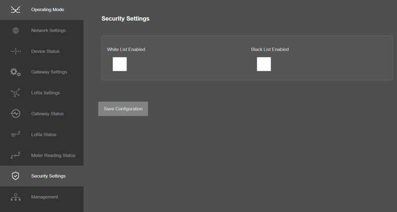
Up to 20 IPs to be filtered are available for any of the list.
Once the setting has been changed, “Save Configuration” button will be enabled.
After clicking button system will tell if the settings applied successfully or not.
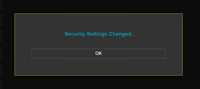
NOTE: Settings will be applied once the device is rebooted from web interface or repowered manually.
From this menu user may change parameters or send command to device
The device restarts itself every 86400 seconds (which means every 24 hours). There are also timeout restart routines in Server mode during listening clients and in Client Mode trying to connect to the server. ( both preset to 10 minutes which means device will restart system if fails to connect a server in Client mode or a client do not connect in preset time in Server mode)
NOTE:
NTP is used to syncronize device time. Device checks if NTP time server is available in every 10 seconds after repower. Device synhcronizes its time if NTP time is available and stops checking after successfull synchronization.
In LoRaWAN versions, device synchronize time with LoRaWAN Server as well after first succesfull connection and it has higher priority than NTP time synchronization. NTP is only used to syncronize device time after a manual or system triggered restarts and it only takes place if NTP time is available and device time difference from NTP time is + or - 24 Hours.
After a firmware change old configuration will be used for minor changes. If a major change occurs system will restore to factory default configuration.
User can change the login information.
User can change the debug level of the device. LKM Series Electricity Meter Protocol to Modbus Protocol Gateways with MQTT has micro USB or USB Type-C and gives log in 115200 - 8N1 format.
Any terminal program can be used to listen the LOG over USB type-C or micro USB port of the device which is recognized as Virtual COM port in PC.
LOG to remote UDP server is also available. If set to UDP server, then LKM will send LOG data to remote UDP server device.
NOTE: Lite Models and Direct Connected to Meter Models do not have Console port for LOG. They still supports LOG to remote UDP.
User can restore to factory settings and force device to reboot. Factory settings restored by clicking "Restore Factory Configuration" button.
In firmware v2.7.0, the actions that restart the device or erase its configuration ask for confirmation before they are carried out. A confirmation window is shown when one of the following buttons is pressed, and the action is performed only after it is confirmed:
"Restore Factory Configuration" : "Restore factory configuration? All settings will be lost."
"Reboot Device" : "Reboot the device?"
"Reboot Alternative Firmware" : "Reboot with the ALTERNATIVE firmware?"
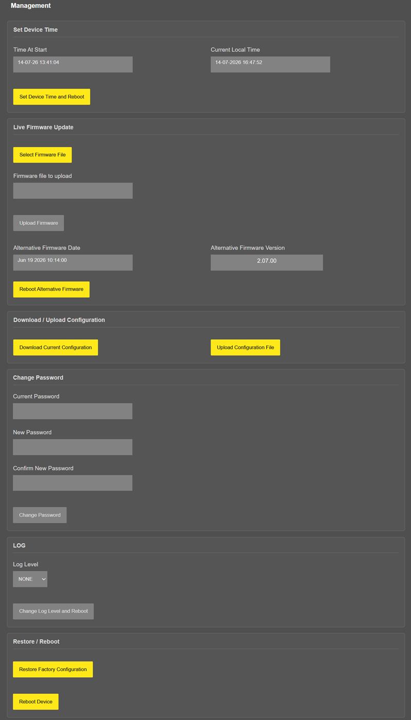
In "Live Firmware Update" part:
Firmware upgrade is possible only with files that REDZ supplied. Once the file selected, LKM shows selected file:
Then “Upload Firmware” button must be clicked. LKM will start to upload file and show status on pop up screen.
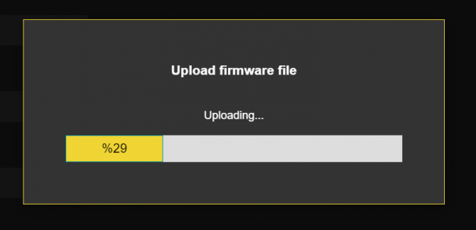
Click "Close" when finished. If somehow LKM fails to upload, refresh webpage and try again please.
After successful upload, LKM will show "Alternative Firmware Date" and "Alternative Firmware Version" data.

Click "Reboot Alternative Firmware" and LKM will reboot with new firmware and show status on screen.
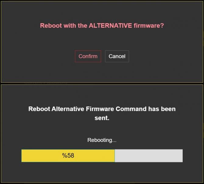
This will take 5 seconds only. Please wait .
Check firmware details from upper part of main screen please if the update firmware procedure finalized properly.
NOTE 1: User must refresh cache of their browser by clicking CTRL+F5 after a succesfull firmware change so that it will force browser to reload web interface (with latest updates/changes).
NOTE 2: In major updates user must also reset device to factory settings.
In "Download / Upload Configuration" part:
User download current configuration of the device to a file or restore a previously defined configuration to device from file.
"Download Current Configuration": Downloads the configuration to a file. It uses "Device Name" for file name and the extensions will be "*.zcfg".
"Download Configuration File": Uploads the configuration from "*.zcfg" file.
In "Log" part:
User may activate Logging and see details of operation. There are different levels of Log with different amount of data.
"None": Logging is closed
"Error": Only errors in systems will be logged
"Info": General info and errors will be logged
"Debug": All details regarding device operation will be logged
If "Console" is selected as output of Log, then micro USB or USB Type-C port of device will be used for logging. Proper cable must be connected and a teminal should be used to receive Log data. As an example "RealTerm" tool can be used.
Simply select COM port and set baud rate 115200 and data type 8N1 and then click open. Device will send log data.
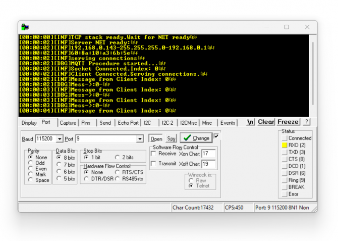
NOTE: Lite Models and Direct Connected to Meter Models do not have Console port for LOG. They still supports LOG to remote UDP.
If "UDP Server" is selected as output of Log, then proper tool must be used to get log data. User must set "UDP Server IP" and "UDP Server Port". Device will send Log to that address. As an example "Package Sender" tool can be used.
Click "File" and then "Settings". Enable "UDP Server" and set the port. Device will send Log data to UDP server.
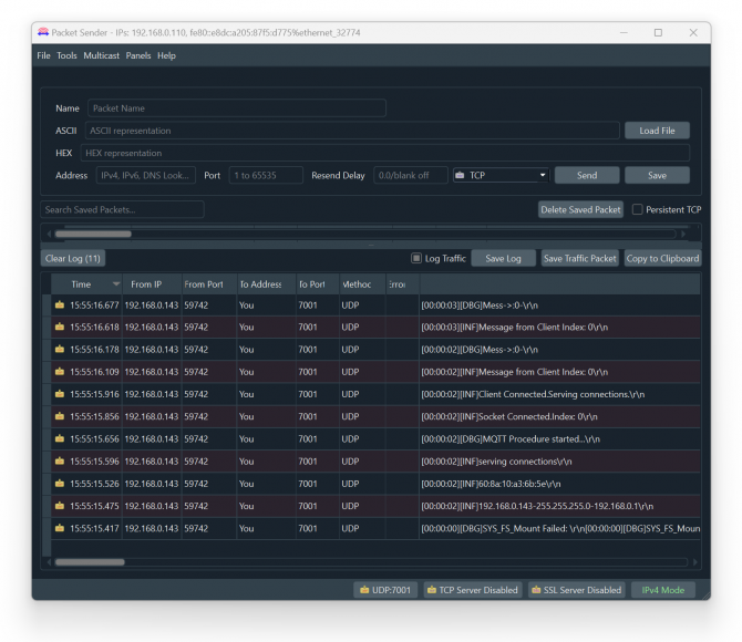
Here is a video example to enable UDP log and receive data via UDP Server software. Video is created with CKL series but applies to all series.
LKM Series Electricity Meter Protocol to Modbus Protocol Gateways with MQTT can read up to 32 IEC 62056-21 (Mode C) and DLMS/COSEM electricity meters via direct RS232 or RS485 connection or connection over optical probe or over TCP/IP. Field devices or applications can get meter data mapped to Modbus registers via Modbus TCP (or Modbus RTU).
LKM Series Electricity Meter Protocol to Modbus Protocol Gateways with MQTT read the data table of IEC 62056-21 (Mode C) and DLMS/COSEM meters and map the following OBIS code data to the following Modbus registers:
NOTE: User can define and enable up to 48 OBIS codes that will be looked for in meter read out list. 24 of them enabled in default list and user can enable base on application needs.
User can edit any OBIS codes that will be looked for in meter read out list and change based on application needs.
| Register Number | OBIS Code | Search String | Register Name | Modbus Address (Dec) | Modbus Address (Hex) | Data Type |
| 1 | F.F | “F.F” | Error Code | 1 | 0x01 | Unsigned Long (UInt32) |
| 2 | 0.9.1 | “0.9.1” | Time | 3 | 0x03 | Unsigned Long (UInt32) |
| 3 | 0.9.2 | “0.9.2” | Date | 5 | 0x05 | Unsigned Long (UInt32) |
| 4 | 1.8.0 | "1.8.0" | Total active energy import A+ | 7 | 0x07 | Unsigned Long (UInt32) |
| 5 | 1.8.1 | "1.8.1" | Total active energy import A+, Tariff 1 | 9 | 0x09 | Unsigned Long (UInt32) |
| 6 | 1.8.2 | "1.8.2" | Total active energy import A+, Tariff 2 | 11 | 0x0B | Unsigned Long (UInt32) |
| 7 | 1.8.3 | "1.8.3" | Total active energy import A+, Tariff 3 | 13 | 0x0D | Unsigned Long (UInt32) |
| 8 | 2.8.0 | "2.8.0" | Total active energy export A- | 15 | 0x0F | Unsigned Long (UInt32) |
| 9 | 2.8.1 | "2.8.1" | Total active energy export A-, Tariff 1 | 17 | 0x11 | Unsigned Long (UInt32) |
| 10 | 2.8.2 | "2.8.2" | Total active energy export A-, Tariff 2 | 19 | 0x13 | Unsigned Long (UInt32) |
| 11 | 2.8.3 | "2.8.3" | Total active energy export A-, Tariff 3 | 21 | 0x15 | Unsigned Long (UInt32) |
| 12 | 5.8.0 | "5.8.0" | Total reactive inductive energy import (Ri+) Q1 | 23 | 0x17 | Unsigned Long (UInt32) |
| 13 | 6.8.0 | "6.8.0" | Total reactive capacitive energy import (Rc+) Q2 | 25 | 0x19 | Unsigned Long (UInt32) |
| 14 | 7.8.0 | "7.8.0" | Total reactive inductive energy export (Ri-) Q3 | 27 | 0x1B | Unsigned Long (UInt32) |
| 15 | 8.8.0 | "8.8.0" | Total reactive capacitive energy export (Rc-) Q4 | 29 | 0x1D | Unsigned Long (UInt32) |
| 16 | 1.6.0 | "1.6.0" | Total maximal average import power P+max | 31 | 0x1F | Unsigned Long (UInt32) |
| 17 | 2.6.0 | "2.6.0" | Total maximal average export power P-max | 33 | 0x21 | Unsigned Long (UInt32) |
| 18 | 32.7.0 | “32.7.0” | L1 Voltage; instantaneous value | 35 | 0x23 | Unsigned Long (UInt32) |
| 19 | 52.7.0 | “52.7.0” | L2 Voltage; instantaneous value | 37 | 0x25 | Unsigned Long (UInt32) |
| 20 | 72.7.0 | “72.7.0” | L3 Voltage; instantaneous value | 39 | 0x27 | Unsigned Long (UInt32) |
| 21 | 31.7.0 | “31.7.0” | L1 Current ; instantaneous value | 41 | 0x29 | Unsigned Long (UInt32) |
| 22 | 51.7.0 | “51.7.0” | L2 Current ; instantaneous value | 43 | 0x2B | Unsigned Long (UInt32) |
| 23 | 71.7.0 | “71.7.0” | L3 Current ; instantaneous value | 45 | 0x2D | Unsigned Long (UInt32) |
| 24 | C.1.0 | “C.1.0” | Meter number / meter ID | 47 | 0x2F | Unsigned Long (UInt32) |
User can edit any OBIS codes that will be looked for in meter read out list and change based on application needs freely from web interface. Here is screenshot for relevant menu
DLMS/COSEM meters use the OBIS codes of their own profile, selected by the meter’s Meter Type. The OBIS code set of each profile is managed from the OBIS Code Settings tabs in the web interface (see Chapter 10).
LKM Series Electricity Meter Protocol to Modbus Protocol Gateways with MQTT meter data can be read by Holding Register command (Function Code 3). Values can be queried individually or as array.
Request
This command is requesting the content of meter data holding registers # 40008 to 40015 from the LKM Series Electricity Meter Protocol to Modbus Protocol Gateways with MQTT with address 1.
0001 0000 0006 01 03 0007 0008
0001: Modbus TCP - Transaction Identifier
0000: Modbus TCP - Protocol Identifier
0006: Modbus TCP - Message Length (6 bytes to follow)
01: The Slave Address (01 hex = address 1 )
03: The Function Code 3 (read the meter read-out data mapped to Modbus)
0007: The Data Address of the first register requested.
(0007 hex = 7 , + 40001 offset = input #40008 )
0008: The total number of registers requested. (read 8 registers for 4 values since each value is 4 bytes, 40006 to 40013)
NOTE: This example shows reading of 1 meter in RS485 bus. If there are more then 1 meter in bus (LKM can read up to 32 meters in same RS485 bus, Lite models can read up to 10 meters and Direct Connected to Meter Models can read the meter it is connected only) then address will be simply incremented by decimal 256
same data address example for other meters:
2nd meter : 0x0107
3th meter : 0x0207
....
10th meter: 0x0907
11th meter: 0x0A07
....
32th meter: 0x1F07
All meters can be read by field Modbus TCP master devices simultaneoulsy over different registers.
Response
0001 0000 0013 01 03 10 0004 9D1F 000E DA50 0007 0AA1 0008 73E3
0001: Modbus TCP - Transaction Identifier
0000: Modbus TCP - Protocol Identifier
0013: Modbus TCP - Message Length (19 bytes to follow)
01: The Slave Address (01 hex = address 1)
03: The Function Code 3 (read the meter read-out data mapped to Modbus)
10: The number of data bytes to follow (4 registers x 4 bytes each = 16 bytes)
0004 9D1F: The contents of register #40008 (1.8.0 value 302367)
000E DA50: The contents of register #40010 (1.8.1 value 973392)
0007 0AA1: The contents of register #40012 (1.8.2 value 461473)
0008 73E3: The contents of register #40014 (1.8.3 value 553955)
Example 1
if read-out data has following line
1.8.0(302.367*MWh)
Read out value is stored at address 0x07 as per Modbus Address Table:
| 1.8.0 | "1.8.0" | Total active energy import A+ | 7 | 0x07 | Unsigned Long (UInt32) |
The read data will be “302367” and user should implement the coefficient to show value properly with or without comma.
Example 2
if read-out data has following line
5.8.0(58.000*MVarh)
Read out value is stored at address 0x17 as per Modbus Address Table:
| 5.8.0 | "5.8.0" | Total reactive inductive energy import (Ri+) Q1 | 23 | 0x17 | Unsigned Long (UInt32) |
The read data will be “58000” and user should implement the coefficient to show value properly with or without comma.
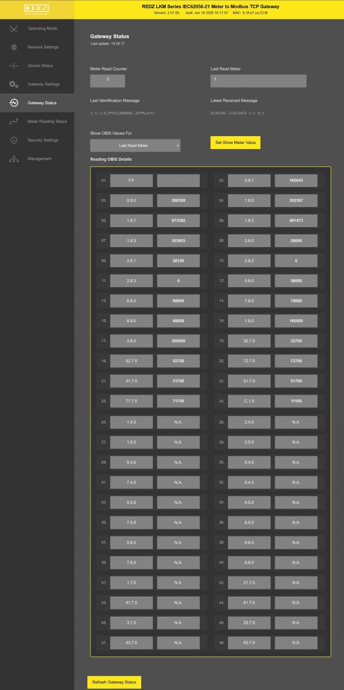
User can cross check those values from "Gateway Status" menu.
NOTE: Data can be negative (with "-" sign). User must interprete that data on their Modbus application accordingly.
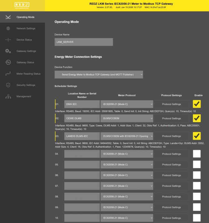
Enter the readout list based on field application. In our example we have 3 meters
Meter 1: Connected via optical interface of meter and start baud rate is 300baud. There is no meter number
Meter 2: Connected directly from RS485 interface of meter and start baud rate is 19200baud with meter number 5061905.
Meter 3: Connected via optical interface of meter and start baud rate is 300baud with meter number ELM82733811.
After entering all details, we also click "Enable" to put that row in to meter read queue.
NOTE: When all meters are connected over RS485, meter number is a must to enter.
In our example we have different implementation so that we can still not enter the meter number of first meter.
Once all settings are entered, click "Save Configuration" and save settings and then click "Reboot Device" under "Management Menu" to restart device with new settings.
NOTE: If the device is busy with meter reading, saving data may delay few seconds for finishing reading meter.
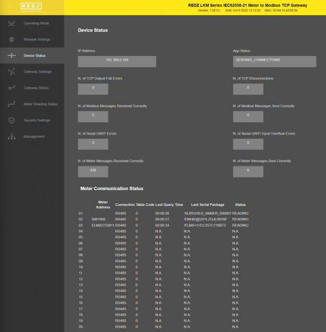
Go to "Device Status" and check if meters are responding by checking "Last Serial Package" data in "Meter Communication Status" list.
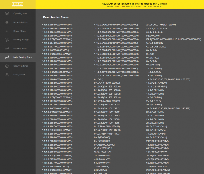
We can also check instantaneous reading result on "Meter Reading Status" menu item.
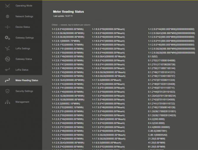
Go to "Gateway Settings" and open another web page for same LKM. Check reading values and adapt OBIS codes based on actual reading values of meter read out list.
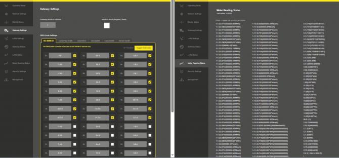
Once changing of OBIS codes complete, click "Save Configuration" to look for new defined OBIS codes.
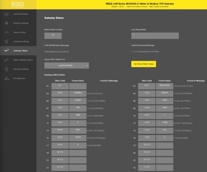
Go to "Gateway Status" menu and check all data is there as per application's need.
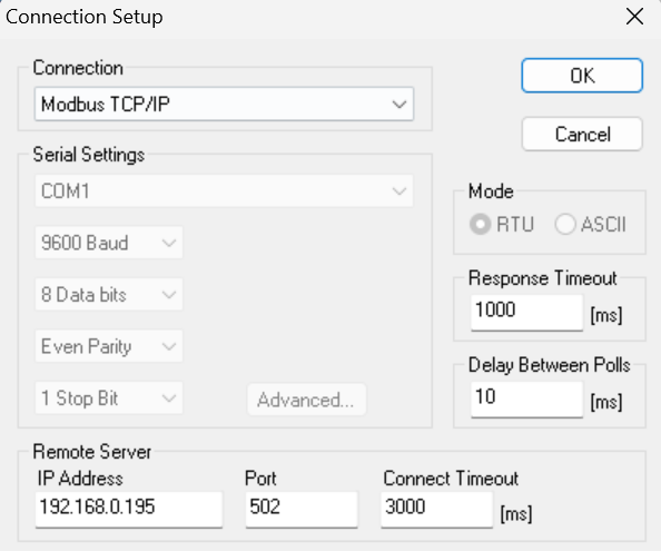
Now LKM is ready to be read via Modbus TCP device or application. We will use "Modbus Poll" software in this application. Open application and connect LKM based on defined TCP/IP and port (or IP released from DHCP server).
In our application we have 3 meters and 24 OBIS codes enabled for each.
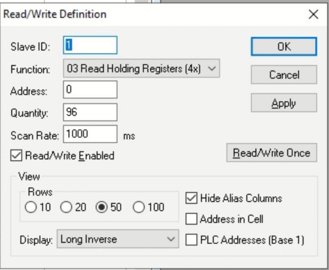
Click "New" and enter Modbus reading details for Meter 1:
Modbus start address will be 0x0000 ( decimal 0) for Meter 1.
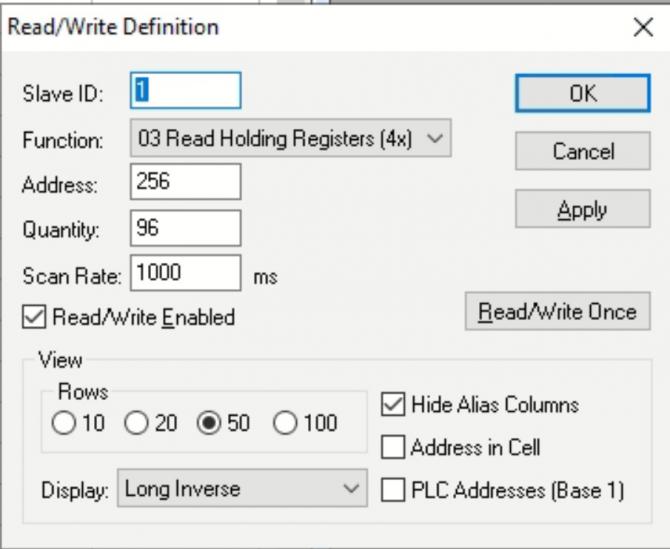
Click "New" again and enter Modbus reading details for Meter 2:
Modbus start address will be 0x0100 ( decimal 256) for Meter 2.
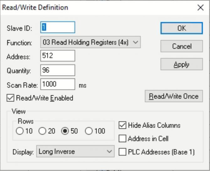
Click "New" again for last time and enter Modbus reading details for Meter 3:
Modbus start address will be 0x0200 ( decimal 512) for Meter 3.
Software will read data based on "Display" settings as follows:
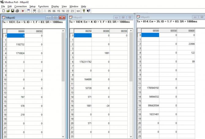
User again cross check data with "Gateway Status" menu.
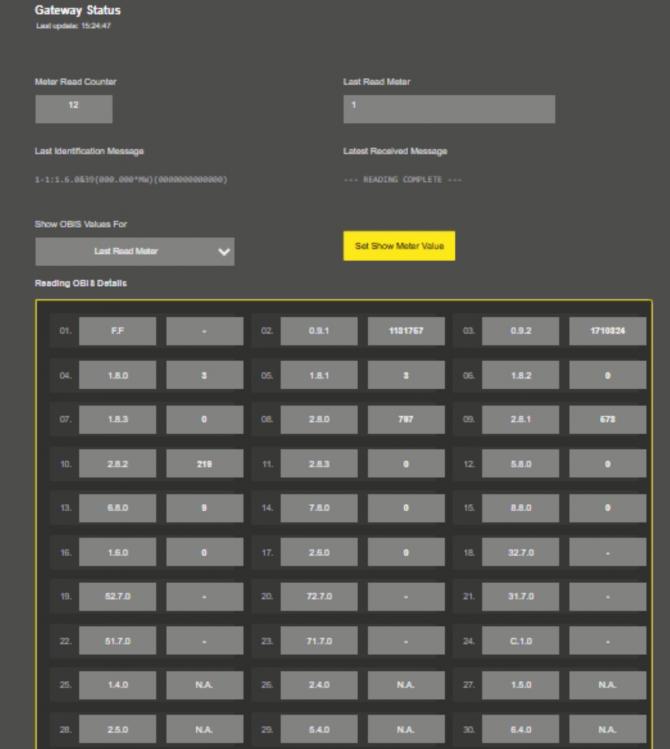
LKM Series Electricity Meter Protocol to Modbus Protocol Gateways with MQTT can read up to 32 IEC 62056-21 (Mode C) and DLMS/COSEM electricity meters via direct RS232 or RS485 connection or connection over optical probe or over TCP/IP. Field devices or applications can get meter data mapped to Modbus registers via Modbus TCP (or Modbus RTU). Simultaneously all meter data can be sent to an MQTT Server.
Enter meter reading details to LKM and make sure all readings are ok.
Please follow details regarding settings and put into operation of LKM is explained in chapter "11.2 Modbus Data Registers Table: Reading Example" for adding meter details and reading meter data.
Then go to "Network Settings" menu and "Enable MQTT Publisher for Enabled Obis Codes" part.
In our example we will use "https://tago.io/" as MQTT Server.
Go to MQTT server panel and click "Add Device" to add LKM to MQTT Server. We will also get password after adding device.
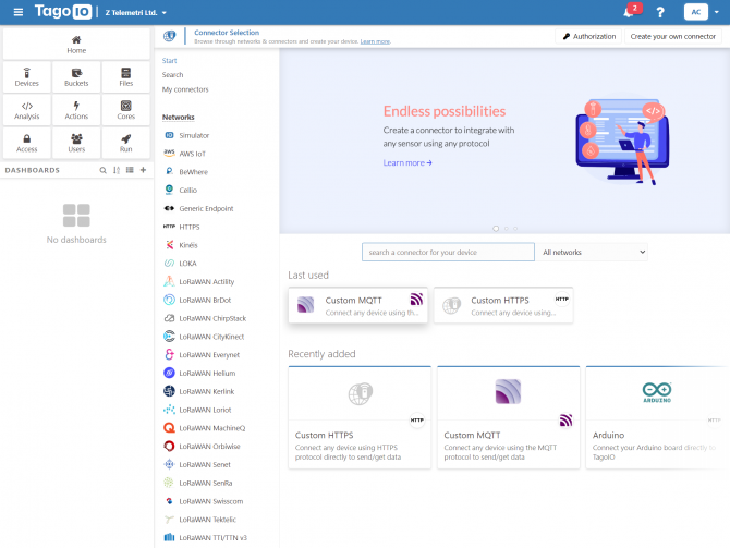
Select "Custom MQTT".
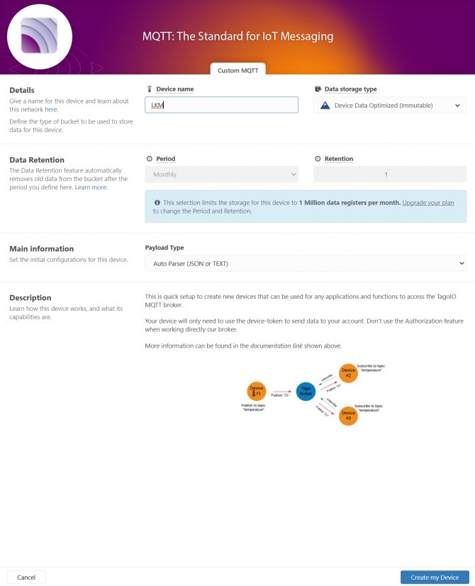
Then enter "Device name" in pop up screen and click "Create My Device".
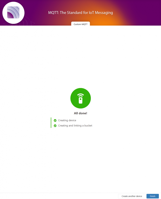
Click "Finish" when all done.
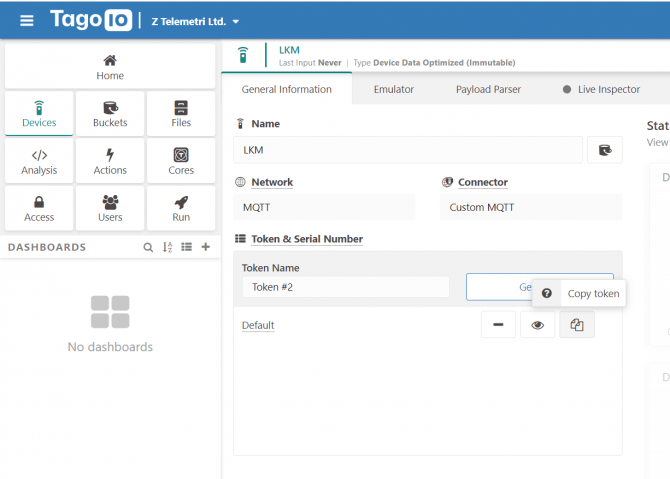
Once the device is created, click "Copy Token" button. This will copy password value.
Then go back to LKM and enter that value as password and click "Save Configuration" button.

"MQTT Broker IP or URL": IP or URL of the MQTT Server. User can enter an IP address or a URL. Maximum length for this field is 64.
75.2.83.130 is IP of "https://tago.io/" web address.
"MQTT Broker Port": TCP Port of the MQTT Server.
1883 is TCP Port of "https://tago.io/" web address.
"Client ID": MQTT Publisher client id. Default is MQTT_LKM_Client.
Maximum length for this field is 32.
"User Name": MQTT Publisher user name. This must be entered based on MQTT server settings.
Maximum length for this field is 64.
"Password": MQTT Publisher password. This must be entered based on MQTT server settings.
Maximum length for this field is 48.
"Publish Topic": MQTT Publisher topic value. Default is MQTT_LKM_Publish_topic.
Maximum length for this field is 32.
"Subscribe Topic": MQTT Publisher subscribe topic value. Default is MQTT_LKM_Subscribe_topic.
Maximum length for this field is 32.
"Minimum Send Interval for a Parsed Data (in seconds)": Minimum value to send meter data to MQTT Server. This time may be longer due to meter quantity in reading queue.
"Data Format": Options for how data is shared by LKM with MQTT server. There are 2 options:
OBIS Values as Objects
OBIS Values as Modbus Frame
When selected as "OBIS Values as Objects", LKM will share data as follows
Device Name, Time (UTC Unix timestamp, added when NTP time is synchronized), Meter Address, Meter Number in Reading List, Data itself in pairs OBIS Code and Matched Value in ASCII readable format
Here is an example:
"F.F" OBIS code is the first one and not read, which is shown as "-"
Next is "0.9.1" OBIS code which is "165043"
Next values can be seen in same manner.
When selected as "OBIS Values as Modbus Frame", LKM will share data as follows
Device Name, Time (UTC Unix timestamp, added when NTP time is synchronized), Meter Address, Meter Number in Reading List, Data itself in hexadecimal format just like a Modbus query response. First byte will show data bytes count and rest is the data itself. For 48 OBIS Codes, there will be 192 bytes.
Here is an example:
C0 in beginning is hexadecimal equivalent for 192 data bytes count
Next is "F.F" OBIS code is not read as shown above which is "00000000"
Next is "0.9.1" OBIS code which is "0002857C" which is 165244 in decimal.
Next values can be seen in same manner.
When all settings are done click "Save Configuration".
Go back to "https://tago.io/" panel and click "Live Inspector" for the LKM and click "Play button".
Data will be shown in real time.
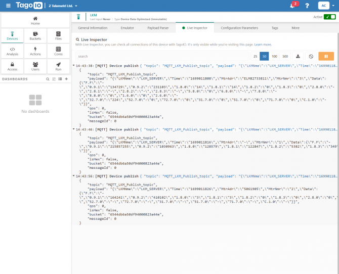
User has to parse and use that parsed data for visualization (for graphs for example) for their application. That is beyond scope of LKM usage.
LKM Series 868MHz LoRaWAN Meter Reader and Electricity Meter Protocol to Modbus Protocol Gateways with MQTT can read up to 32 pieces of IEC 62056-21 (Mode C) and DLMS/COSEM electricity meters via direct RS232 or RS485 connection or connection over optical probe or over TCP/IP. All read meter data can be sent to a LoRaWAN Server. Simultaneously field devices or applications can get meter data mapped to Modbus registers via Modbus TCP (or Modbus RTU) and all meter data can also be sent to an MQTT Server.
We used The "Things Network" as LoRaWAN Server in this application.
Enter meter reading details to LKM and make sure all readings are ok.
Please follow details regarding settings and put into operation of LKM is explained in chapter "11.2 Modbus Data Registers Table: Reading Example" for adding meter details and reading meter data.
Then go to "LoRa Settings" menu.
Next step will be configuring the settings for LoRaWAN server.
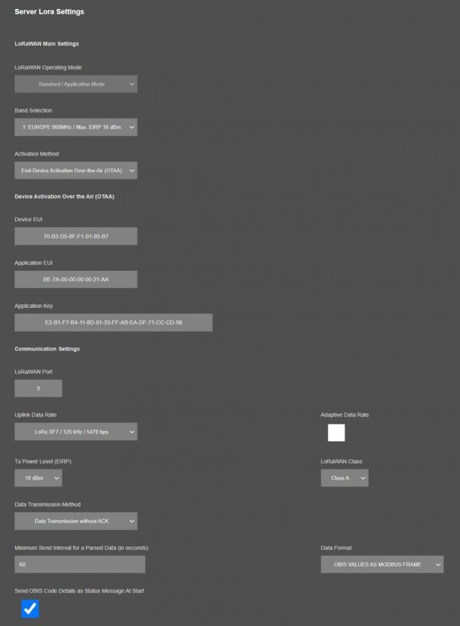
Activation Method: We selected End-Device Activation Over-the-Air (OTAA) method for this example. Activation by Personalization (ABP) can also be selected if needed.
Also, device is defined in The Things Network LoRaWAN Server with this specific Device EUI 70-B3-D5-8F-F1-01-85-B7
Application Key and Aplication EUI: Values entered based on values in The Things Network LoRaWAN Server.
LoRaWAN Port: Port is selected for this Application.
Port 1 is used by LKM Device Status info
Port 2 is used by OBIS Status info
Port 3 is used to send Meter Read data as default however any number between 3 and 255 can be entered here based on Application needs.
Data Rate and Other Settings: We selected SF7 data rate so that LKM can send with fastest Uplink Data Rate to LoRaWAN server side. Other settings are available based on Application needs. In this example LoRaWAN Class C is used.
"Minimum Send Interval for a Parsed Data (in seconds)": Minimum value to send meter data to MQTT Server. This time may be longer than selected value due to meter quantity in reading queue. We prefered 60seconds in this example..
"Data Format": Options for how data is shared by LKM with LoRaWAN server. There is 1 option for now:
Parsed Data as Modbus Frame
"Send OBIS Code Details as Status Message At Start": If enabled, LKM will send status message for enabled/configured OBIS codes in system to LoRaWAN Server. If not needed, it can be disabled. We enabled for this example.
Click Save Configuration when all settings are done and Restart device with command under Management menu.
In The Things Network LoRaWAN Server website, click "+ Register end device" and select "Enter end device specifics manually" and select following options:
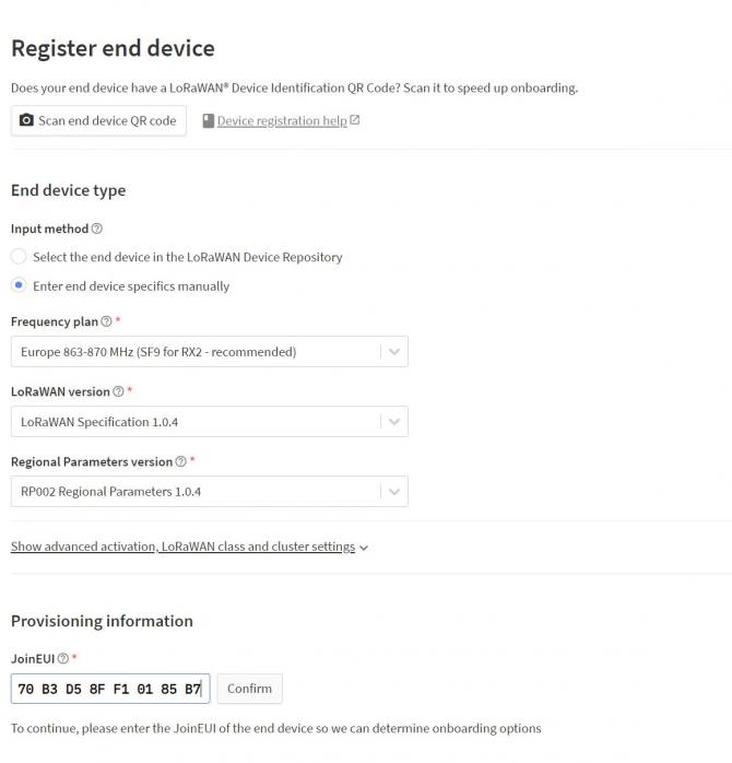
Specify Join EUI and click confirm. This must be unique number for joining LoRaWAN Server.
Then enter the Device EUI 70-B3-D5-8F-F1-01-85-B7 in this example and generate AppKey.
Click "Register end device" once finished.
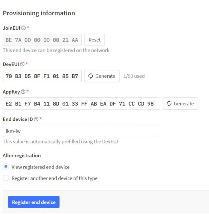
Created device will be shown on screen.
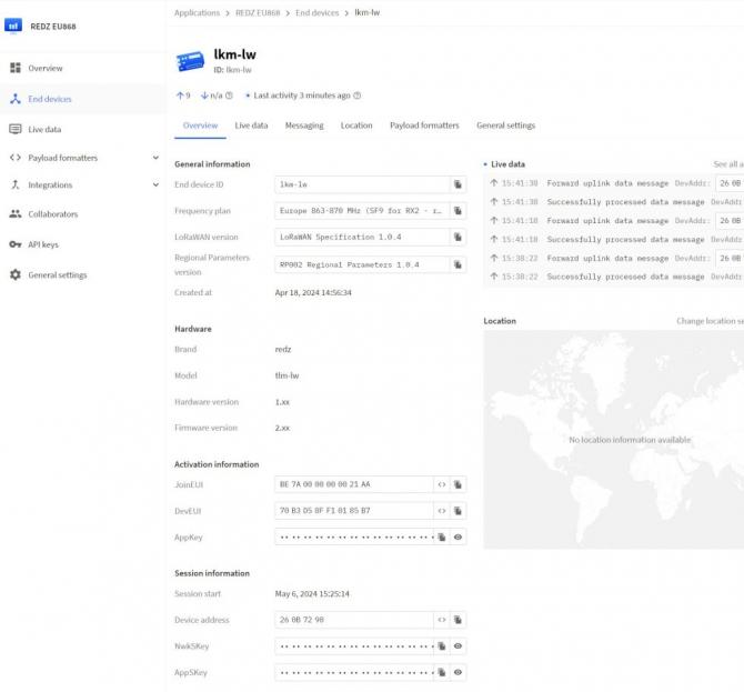
LKM now can send data to LoRaWAN Server.
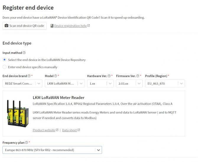
In The Things Network LoRaWAN Server website, click "+ Register end device" and select "Select the end device in the LoRaWAN Device Repository". Then search for REDZ brand and select it as follows.
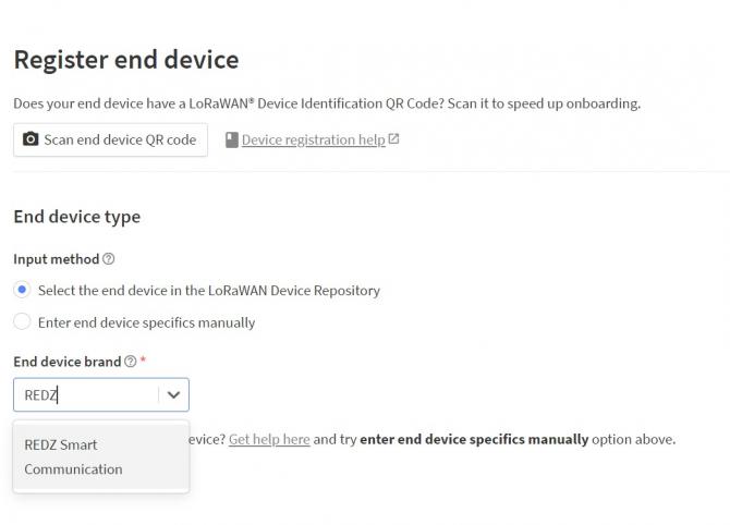
Select the model, hardware version, firmware version, profile and frequency plan:
Specify Join EUI and click confirm. This must be unique number for joining LoRaWAN Server.
Then enter the Device EUI 70-B3-D5-8F-F1-01-85-B7 in this example and generate AppKey.
Click "Register end device" once finished.
Created device will be shown on screen.
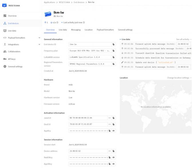
LKM now can send data to LoRaWAN Server.
LoRaWAN device activation can be monitored from LKM LoRa Status page.
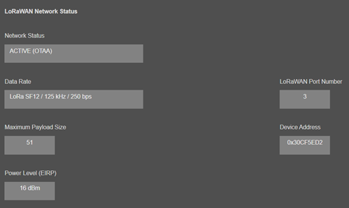
Once the device is Active, it will start reading electricity meters and send data to LoRaWAN Server.
If Activation takes longer than expected, user can also activate device LOG and try check details over console or UDP server log.
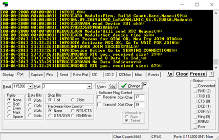
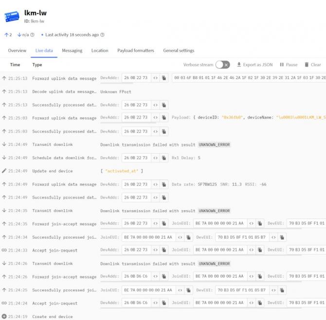
The Things Network LoRaWAN Server website "Live Data" can also be checked if LKM is sending data.
Go to "Device Status" and check if meters are responding by checking "Last Serial Package" data in "Meter Communication Status" list.
We can also check instantaneous reading result on "Meter Reading Status" menu item.
Go to "Gateway Status" menu and check all data is there as per application's need. If OBIS needs to be changed then please change OBIS codes and recheck reading status. Now the data is ready to be sent to LoRaWAN Server.
There are 2 Status Messages available, 1 sent in every connection to LoRaWAN Server, the other is optional.
Status Message - Device Status
Message sent to LoRaWAN Port number 1 in every connection to LoRaWAN Server
4 Bytes: LKM unique Device Id
1 Byte: Frame Type (Lower 4 bits) and Package Number (Upper 4 bits). If Package Number is 1 or more that means the package splitted.
0x00 : means status package for device status and package is the first package
1 Byte: Number of Meters configured to be read
6 Bytes: Number of enabled OBIS Codes, one byte per OBIS profile (in order: IEC 62056-21, Landis+Gyr DLMS, Actaris/Itron, Iskra DLMS, Cewe DLMS, Generic DLMS)
1 Byte: LoRaWAN Port of the response package
4 Bytes: RTC Time
3 Bytes: LKM Device firmware version
N Bytes (maximum 22): LKM Device name configured by user
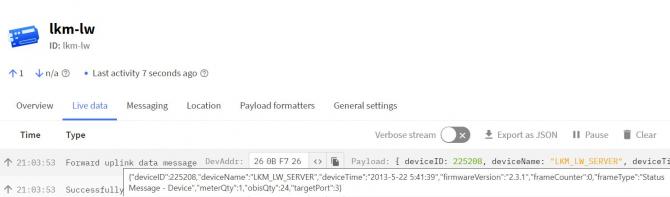
Here is an example byte can be received by Server side:
0003BFEB 00 01 18 30 30 30 30 30 03 688C7B8D 020700 4C4B4D5F4C575F534552564552
|
Number |
Byte Count | Data | Explanation | Example (Hex) |
| 1 | 4 Bytes | Device ID |
Unique ID of the device that is shown on Operating Mode page |
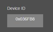
0003BFEB |
| 2 | 1 Byte | Frame Details |
Gives detail of frame and frame counter
0x0X: Frame counter, this is first frame |
00 |
| 3 | 1 Byte | Number of Meters Configured to be read |
1 Meter is being read by LKM |
01 |
| 4 | 6 Bytes | Number of OBIS Codes per Profile | One byte per OBIS profile, in order: IEC 62056-21, Landis+Gyr DLMS, Actaris/Itron, Iskra DLMS, Cewe DLMS, Generic DLMS. Here 0x18 = 24 codes are enabled in the IEC 62056-21 profile and 0x30 = 48 codes in each DLMS profile. The meter in this example is read with the Actaris/Itron profile (48 codes). | 18 30 30 30 30 30 |
| 5 | 1 Byte | Target Port | LoraWAN Port that will be used to send meter data | 03 |
| 6 | 4 Bytes | Device Date Time |
Device date time, sample function to parse this data is given in Payload Formatter part.
|
688C7B8D |
| 7 | 3 Bytes | Firmware Version | Firmware version of LKM usedIt is "02.07.00" | 020700 |
| 8 | Remaining Bytes (max 22) | Device Name |
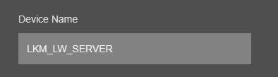
LKM Device Name that is shown on Operating Mode page It is "LKM_LW_SERVER" |
4C4B4D5F4C575F534552564552 |
Here is example screen from The Things Network LoRaWAN Server website:
Status Message - OBIS Details
Message sent to LoRaWAN Port number 1 in every connection to LoRaWAN Server if enabled by user.
4 Bytes: LKM unique Device Id
1 Byte: Frame Type (Lower 4 bits) and Package Number (Upper 4 bits). If Package Number is 1 or more that means the package splitted.
0x01 : means status package for OBIS details and package is the first package
OBIS frames are shared one after another in the following fixed 8-byte format; the total number of frames equals the sum of the per-profile OBIS counts given in the Device Status message:
1 Byte: OBIS Profile (0 = IEC 62056-21, 1 = Landis+Gyr DLMS, 2 = Actaris/Itron, 3 = Iskra DLMS, 4 = Cewe DLMS, 5 = Generic DLMS)
1 Byte: OBIS Code Number (1-48), in the same sequence configured from the web interface
6 Bytes: the OBIS code itself as 6 octets A.B.C.D.E.F, each octet one byte (binary, not ASCII)
....Next OBIS frame, as many as the maximum payload size allows.
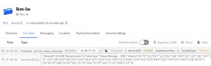
Here is an example byte can be received by Server side:
0003BFEB 01 02 01 00 00 01 00 00 FF 02 02 00 00 60 01 FF FF 02 03 01 01 01 08 00 FF 02 04 01 01 02 08 00 FF 02 05 01 01 03 08 00 FF 02 06 01 01 04 08 00 FF 02 07 01 01 05 08 00 FF 02 08 01 01 06 08 00 FF 02 09 01 01 07 08 00 FF 02 0A 01 01 08 08 00 FF 02 0B 01 01 09 08 00 FF 02 0C 01 01 0A 08 00 FF 02 0D 01 01 01 08 01 FF 02 0E 01 01 01 08 02 FF 02 0F 01 01 01 08 03 FF 02 10 01 01 02 08 01 FF 02 11 01 01 02 08 02 FF 02 12 01 01 02 08 03 FF 02 13 01 01 80 08 01 FF 02 14 01 01 82 08 01 FF 02 15 01 01 05 08 01 FF 02 16 01 01 06 08 01 FF 02 17 01 01 07 08 01 FF 02 18 01 01 08 08 01 FF 02 19 01 01 01 09 01 FF 02 1A 01 01 01 09 02 FF 02 1B 01 01 02 09 01 FF 02 1C 01 01 02 09 02 FF 02 1D 01 01 03 09 01 FF 02 1E 01 01 03 09 02 FF 02 1F 01 01 04 09 01 FF 02 20 01 01 04 09 02 FF 02 21 01 01 01 07 00 FF 02 22 01 01 02 07 00 FF 02 23 01 01 03 07 00 FF 02 24 01 01 04 07 00 FF 02 25 01 01 05 07 00 FF 02 26 01 01 06 07 00 FF 02 27 01 01 07 07 00 FF 02 28 01 01 08 07 00 FF 02 29 01 01 1F 07 00 FF 02 2A 01 01 33 07 00 FF 02 2B 01 01 47 07 00 FF 02 2C 01 01 20 07 00 FF 02 2D 01 01 34 07 00 FF 02 2E 01 01 48 07 00 FF 02 2F 00 00 62 85 3D FF 02 30 00 00 62 85 3E FF
| Number | Byte Count | Data | Explanation | Example (Hex) |
| 1 | 4 Bytes | Device ID | Unique ID of the device | 0003BFEB |
| 2 | 1 Byte | Frame Details | 0xX1: OBIS Details frame. Upper nibble = package number (first package here, so 0). | 01 |
| 3 | 1 Byte | OBIS Profile | Profile of the OBIS code (02 = Actaris/Itron) | 02 |
| 4 | 1 Byte | OBIS Code Number | it is "1" | 01 |
| 5 | 6 Bytes | OBIS Code | it is "0.0.1.0.0.255" | 00 00 01 00 00 FF |
| 6 | 1 Byte | OBIS Profile | Profile of the OBIS code (02 = Actaris/Itron) | 02 |
| 7 | 1 Byte | OBIS Code Number | it is "2" | 02 |
| 8 | 6 Bytes | OBIS Code | it is "0.0.96.1.255.255" | 00 00 60 01 FF FF |
| … | … | … | Every OBIS code is sent as a fixed 8-byte record (1 byte profile + 1 byte number + 6 octets) | … |
| 72 | 1 Byte | OBIS Profile | Profile of the OBIS code (02 = Actaris/Itron) | 02 |
| 48 | 1 Byte | OBIS Code Number | it is "48" | 30 |
| 74 | 6 Bytes | OBIS Code | it is "0.0.98.133.62.255" | 00 00 62 85 3E FF |
Here is example screen from The Things Network LoRaWAN Server website:
Meter Data Message - Parsed from Meter Reading
Message sent to LoRaWAN configured Port (default is 3) and minimum send interval can be configured by user
4 Bytes: LKM unique Device Id
1 Byte: Frame Type (Lower 4 bits) and Package Number (Upper 4 bits). If Package Number is 1 or more that means the package splitted.
0x02: means meter data package and package is the first package
1 Byte: Read Meter number in same sequence configured from web interface
1 Byte: Data Starting OBIS Code Number in same sequence configured from web interface
1 Byte: Total Data Size in Payload
Meter Data values are shared one after another, each value in a fixed 4-byte format (UInt32)
4 Bytes: Meter Data
....Next data that maximum payload size allows
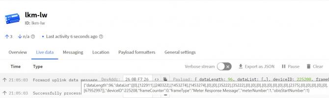
Here is an example byte can be received by Server side:
0003BFEB 02 01 01 C0 6A49315B03DFF02400AAEDD000BCE378001A7D40001238100010E05000099CF0000BEAC80006496000B7BB280000000000AA32500000B7980000000000BCE378000000000000000000000000000000000000000000000000000000000000000000000000000000000000000000000000000000000000000000000000000000000000000000000000000000000000000000000000000000000000000000000000000003E8000003E800002328000E5BC800000BB8000003E80000000000000000
|
Number |
Byte Count | Data | Explanation | Example (Hex) |
| 1 | 4 Bytes | Device ID |
Unique ID of the device that is shown on Operating Mode page |
0003BFEB |
| 2 | 1 Byte | Frame Details |
Gives detail of frame and frame counter
0x0X: Frame counter, this is first frame |
02 |
| 3 | 1 Byte | Read Meter Number |
Meter number that the reading belongs to. it is "1" |
01 |
| 4 | 1 Byte | Data Starting OBIS Code Number |
OBIS code number for data frame first data and the next ones continues as defined in LKM consequently it is "1" |
01 |
| 5 | 1 Byte | Total Data Size | total data bytes count. It is "192" (0xC0) in this example. Each data is 4 bytes so there are 48 data available. | C0 |
| 6 | 4 Bytes | Meter Data: 1 | it is "1783181659" (0.0.1.0.0.255, Clock) | 6A49315B |
| 7 | 4 Bytes | Meter Data: 2 | it is "65007652" (0.0.96.1.255.255, Serial Number) | 03DFF024 |
| ....... | ....... | ....... |
Every Meter data parsed in same way |
....... |
| 53 | 4 Bytes | Meter Data: 48 | it is "0" (0.0.98.133.62.255) | 00000000 |
Here is example screen from The Things Network LoRaWAn Server website:
LKM Series 868MHz LoRaWAN Meter Reader and Electricity Meter Protocol to Modbus Protocol Gateways with MQTT has unique feature to resize frames for LoRaWAN and also unique feature to calculate duty cycles based on LoRaWAN duty cycle limitations. Users do not need to worry on query interval or response size, LKM Series 868MHz LoRaWAN Meter Reader and Electricity Meter Protocol to Modbus Protocol Gateways with MQTT automatically split and send read data.
Here is example Status Message - OBIS Details
0003BFEB 01 02 01 00 00 01 00 00 FF 02 02 00 00 60 01 FF FF 02 03 01 01 01 08 00 FF 02 04 01 01 02 08 00 FF 02 05 01 01 03 08 00 FF 02 06 01 01 04 08 00 FF 02 07 01 01 05 08 00 FF 02 08 01 01 06 08 00 FF 02 09 01 01 07 08 00 FF 02 0A 01 01 08 08 00 FF 02 0B 01 01 09 08 00 FF 02 0C 01 01 0A 08 00 FF 02 0D 01 01 01 08 01 FF 02 0E 01 01 01 08 02 FF 02 0F 01 01 01 08 03 FF 02 10 01 01 02 08 01 FF 02 11 01 01 02 08 02 FF 02 12 01 01 02 08 03 FF 02 13 01 01 80 08 01 FF 02 14 01 01 82 08 01 FF 02 15 01 01 05 08 01 FF 02 16 01 01 06 08 01 FF 02 17 01 01 07 08 01 FF 02 18 01 01 08 08 01 FF 02 19 01 01 01 09 01 FF 02 1A 01 01 01 09 02 FF 02 1B 01 01 02 09 01 FF 02 1C 01 01 02 09 02 FF 02 1D 01 01 03 09 01 FF 02 1E 01 01 03 09 02 FF 02 1F 01 01 04 09 01 FF 02 20 01 01 04 09 02 FF 02 21 01 01 01 07 00 FF 02 22 01 01 02 07 00 FF 02 23 01 01 03 07 00 FF 02 24 01 01 04 07 00 FF 02 25 01 01 05 07 00 FF 02 26 01 01 06 07 00 FF 02 27 01 01 07 07 00 FF 02 28 01 01 08 07 00 FF 02 29 01 01 1F 07 00 FF 02 2A 01 01 33 07 00 FF 02 2B 01 01 47 07 00 FF 02 2C 01 01 20 07 00 FF 02 2D 01 01 34 07 00 FF 02 2E 01 01 48 07 00 FF 02 2F 00 00 62 85 3D FF 02 30 00 00 62 85 3E FF
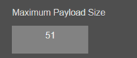
Maximum Payload size can be seen in LoRa Status page which is 51 bytes in this example:
LKM automatically divides data and send to LoRaWAN Server split messages and wait to send next part until duty cycle is available.
Device console LOG will show details for the long frame and information regarding package split and duty cycle wait.
Here is how data is splitted:
Message 1: 0003BFEB 01 02 01 00 00 01 00 00 FF 02 02 00 00 60 01 FF FF 02 03 01 01 01 08 00 FF 02 04 01 01 02 08 00 FF 02 05 01 01 03 08 00 FF 02 06 01 01 04 08 00 FF 02 07 01 01 05 08 00 FF 02 08 01 01 06 08 00 FF 02 09 01 01 07 08 00 FF 02 0A 01 01 08 08 00 FF 02 0B 01 01 09 08 00 FF 02 0C 01 01 0A 08 00 FF 02 0D 01 01 01 08 01 FF 02 0E 01 01 01 08 02 FF 02 0F 01 01 01 08 03 FF 02 10 01 01 02 08 01 FF 02 11 01 01 02 08 02 FF 02 12 01 01 02 08 03 FF 02 13 01 01 80 08 01 FF 02 14 01 01 82 08 01 FF 02 15 01 01 05 08 01 FF 02 16 01 01 06 08 01 FF 02 17 01 01 07 08 01 FF 02 18 01 01 08 08 01 FF 02 19 01 01 01 09 01 FF 02 1A 01 01 01 09 02 FF 02 1B 01 01 02 09 01 FF 02 1C 01 01 02 09 02 FF 02 1D 01 01 03 09 01 FF
| Number | Byte Count | Data | Explanation | Example (Hex) |
| 1 | 4 Bytes | Device ID | Unique ID of the device | 0003BFEB |
| 2 | 1 Byte | Frame Details | 0xX1 OBIS Details frame; upper nibble is the package number (0 = first package). | 01 |
| 3 | 1 Byte | OBIS Profile | Profile of the OBIS code (02 = Actaris/Itron) | 02 |
| 4 | 1 Byte | OBIS Code Number | it is "1" | 01 |
| 5 | 6 Bytes | OBIS Code | it is "0.0.1.0.0.255" | 00 00 01 00 00 FF |
| 6 | 1 Byte | OBIS Profile | Profile of the OBIS code (02 = Actaris/Itron) | 02 |
| 7 | 1 Byte | OBIS Code Number | it is "2" | 02 |
| 8 | 6 Bytes | OBIS Code | it is "0.0.96.1.255.255" | 00 00 60 01 FF FF |
| … | … | … | The remaining OBIS codes in this package follow the same 8-byte record format | … |
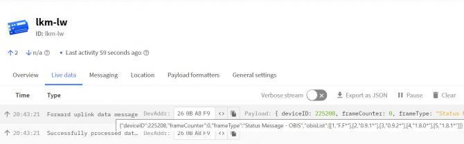
Here is example screen from The Things Network LoRaWAN Server website:
Message 2:
0003BFEB 11 02 1E 01 01 03 09 02 FF 02 1F 01 01 04 09 01 FF 02 20 01 01 04 09 02 FF 02 21 01 01 01 07 00 FF 02 22 01 01 02 07 00 FF 02 23 01 01 03 07 00 FF 02 24 01 01 04 07 00 FF 02 25 01 01 05 07 00 FF 02 26 01 01 06 07 00 FF 02 27 01 01 07 07 00 FF 02 28 01 01 08 07 00 FF 02 29 01 01 1F 07 00 FF 02 2A 01 01 33 07 00 FF 02 2B 01 01 47 07 00 FF 02 2C 01 01 20 07 00 FF 02 2D 01 01 34 07 00 FF 02 2E 01 01 48 07 00 FF 02 2F 00 00 62 85 3D FF 02 30 00 00 62 85 3E FF
| Number | Byte Count | Data | Explanation | Example (Hex) |
| 1 | 4 Bytes | Device ID | Unique ID of the device | 0003BFEB |
| 2 | 1 Byte | Frame Details | 0xX1 OBIS Details frame; upper nibble is the package number (1 = second package). | 11 |
| 3 | 1 Byte | OBIS Profile | Profile of the OBIS code (02 = Actaris/Itron) | 02 |
| 4 | 1 Byte | OBIS Code Number | it is "30" | 1E |
| 5 | 6 Bytes | OBIS Code | it is "1.1.3.9.2.255" | 01 01 03 09 02 FF |
| 6 | 1 Byte | OBIS Profile | Profile of the OBIS code (02 = Actaris/Itron) | 02 |
| 7 | 1 Byte | OBIS Code Number | it is "31" | 1F |
| 8 | 6 Bytes | OBIS Code | it is "1.1.4.9.1.255" | 01 01 04 09 01 FF |
| … | … | … | The remaining OBIS codes in this package follow the same 8-byte record format | … |
Here is example screen from The Things Network LoRaWAN Server website:
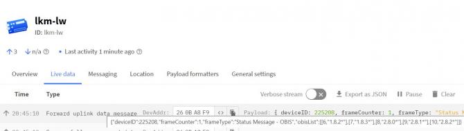
Here is example Meter Response Message
0003BFEB 02 01 01 C0 6A49315B03DFF02400AAEDD000BCE378001A7D40001238100010E05000099CF0000BEAC80006496000B7BB280000000000AA32500000B7980000000000BCE378000000000000000000000000000000000000000000000000000000000000000000000000000000000000000000000000000000000000000000000000000000000000000000000000000000000000000000000000000000000000000000000000000003E8000003E800002328000E5BC800000BB8000003E80000000000000000
Here is how data is splitted:
Message 1:
0003BFEB 02 01 01 28 6A49315B03DFF02400AAEDD000BCE378001A7D40001238100010E05000099CF0000BEAC800064960
|
Number |
Byte Count | Data | Explanation | Example (Hex) |
| 1 | 4 Bytes | Device ID | Unique ID of the device that is shown on Operating Mode page | 0003BFEB |
| 2 | 1 Byte | Frame Details | 0xX2: Meter Response frame. Upper nibble = package number (0 = first package). | 02 |
| 3 | 1 Byte | Read Meter Number |
Meter number that the reading belongs to. it is "1" |
01 |
| 4 | 1 Byte | Data Starting OBIS Code Number | OBIS code number of the first data value in this package. | 01 |
| 5 | 1 Byte | Total Data Size | total data bytes count. It is "40" (0x28) in this example. Each data is 4 bytes so there are 10 data available. | 28 |
| 6 | 4 Bytes | Meter Data: 1 | it is "1783181659" (0.0.1.0.0.255, Clock) | 6A49315B |
| ....... | ....... | ....... |
Every Meter data parsed in same way |
....... |
| 15 | 4 Bytes | Meter Data: 10 | it is "412000" (1.1.8.8.0.255) | 00064960 |
(to be updated) Here is example screen from The Things Network LoRaWAN Server website:
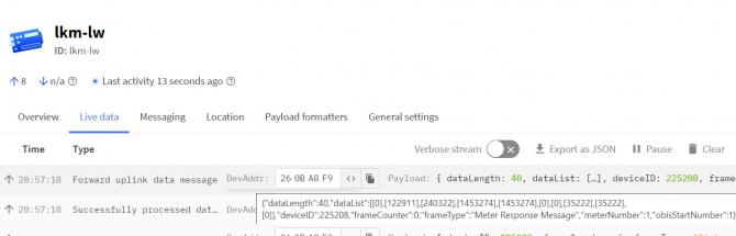
Message 2:
0003BFEB 12 01 0B 28 00B7BB280000000000AA32500000B7980000000000BCE37800000000000000000000000000000000
|
Number |
Byte Count | Data | Explanation | Example (Hex) |
| 1 | 4 Bytes | Device ID | Unique ID of the device that is shown on Operating Mode page | 0003BFEB |
| 2 | 1 Byte | Frame Details | 0xX2: Meter Response frame. Upper nibble = package number (1 = second package). | 12 |
| 3 | 1 Byte | Read Meter Number |
Meter number that the reading belongs to. it is "1" |
01 |
| 4 | 1 Byte | Data Starting OBIS Code Number | OBIS code number of the first data value in this package. | 0B |
| 5 | 1 Byte | Total Data Size | total data bytes count. It is "40" (0x28) in this example. Each data is 4 bytes so there are 10 data available. | 28 |
| 6 | 4 Bytes | Meter Data: 11 | it is "12041000" (1.1.9.8.0.255) | 00B7BB28 |
| ....... | ....... | ....... |
Every Meter data parsed in same way |
....... |
| 15 | 4 Bytes | Meter Data: 20 | it is "0" (1.1.130.8.1.255) | 00000000 |
(to be updated) Here is example screen from The Things Network LoRaWAN Server website:
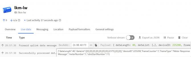
Message 3:
0003BFEB 22 01 15 28 00000000000000000000000000000000000000000000000000000000000000000000000000000000
| Number | Byte Count | Data | Explanation | Example (Hex) |
| 1 | 4 Bytes | Device ID | Unique ID of the device that is shown on Operating Mode page | 0003BFEB |
| 2 | 1 Byte | Frame Details | 0xX2: Meter Response frame. Upper nibble = package number (2 = third package). | 22 |
| 3 | 1 Byte | Read Meter Number | Meter number that the reading belongs to. it is "1" | 01 |
| 4 | 1 Byte | Data Starting OBIS Code Number | OBIS code number of the first data value in this package. | 15 |
| 5 | 1 Byte | Total Data Size | total data bytes count. It is "40" (0x28) in this example. Each data is 4 bytes so there are 10 data available. | 28 |
| 6 | 4 Bytes | Meter Data: 21 | it is "0" (1.1.1.7.0.255) | 00000000 |
| ....... | ....... | ....... | Every Meter data parsed in same way | ....... |
| 15 | 4 Bytes | Meter Data: 30 | it is "0" (1.1.3.9.2.255) | 00000000 |
(to be updated) Here is example screen from The Things Network LoRaWAN Server website:
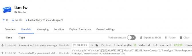
Message 4:
0003BFEB 32 01 1F 28 00000000000000000000000000000000000000000000000000000000000000000000000000000000
| Number | Byte Count | Data | Explanation | Example (Hex) |
| 1 | 4 Bytes | Device ID | Unique ID of the device that is shown on Operating Mode page | 0003BFEB |
| 2 | 1 Byte | Frame Details | 0xX2: Meter Response frame. Upper nibble = package number (3 = fourth package). | 32 |
| 3 | 1 Byte | Read Meter Number | Meter number that the reading belongs to. it is "1" | 01 |
| 4 | 1 Byte | Data Starting OBIS Code Number | OBIS code number of the first data value in this package. | 1F |
| 5 | 1 Byte | Total Data Size | total data bytes count. It is "40" (0x28) in this example. Each data is 4 bytes so there are 10 data available. | 28 |
| 6 | 4 Bytes | Meter Data: 31 | it is "0" (1.1.4.9.1.255) | 00000000 |
| ....... | ....... | ....... | Every Meter data parsed in same way | ....... |
| 15 | 4 Bytes | Meter Data: 40 | it is "0" (1.1.8.7.0.255) | 00000000 |
(to be updated) Here is example screen from The Things Network LoRaWAN Server website:
Message 5:
0003BFEB 42 01 29 20 000003E8000003E800002328000E5BC800000BB8000003E80000000000000000
| Number | Byte Count | Data | Explanation | Example (Hex) |
| 1 | 4 Bytes | Device ID | Unique ID of the device that is shown on Operating Mode page | 0003BFEB |
| 2 | 1 Byte | Frame Details | 0xX2: Meter Response frame. Upper nibble = package number (4 = fifth package). | 42 |
| 3 | 1 Byte | Read Meter Number | Meter number that the reading belongs to. it is "1" | 01 |
| 4 | 1 Byte | Data Starting OBIS Code Number | OBIS code number of the first data value in this package. | 29 |
| 5 | 1 Byte | Total Data Size | total data bytes count. It is "32" (0x20) in this example. Each data is 4 bytes so there are 8 data available. | 20 |
| 6 | 4 Bytes | Meter Data: 41 | it is "1000" (1.1.31.7.0.255) | 000003E8 |
| ....... | ....... | ....... | Every Meter data parsed in same way | ....... |
| 15 | 4 Bytes | Meter Data: 48 | it is "0" (0.0.98.133.62.255) | 00000000 |
(to be updated) Here is example screen from The Things Network LoRaWAN Server website:
This payload formatter applies to firmware versions before v2.7.0 (Status message carries a single OBIS count byte; OBIS codes are sent as ASCII text with 0x1F separators). Here is the code used in The Things Network (TTN):
function decodeUplink(input) {
  switch (input.fPort) {
    case 1:
      return {
        // Decoded data
        data: {
          deviceID: ((input.bytes[0] << 24) + (input.bytes[1] << 16) + (input.bytes[2] << 8) + (input.bytes[3])),
          frameType: getFrameType(input.bytes[4] & 0x0F),
          frameCounter: ((input.bytes[4] >> 4) & 0x0F),
          meterQty: input.bytes[5],
obisQty: input.bytes[6],
targetPort: input.bytes[7],
deviceTime: get_status_time((input.bytes[8] << 24) + (input.bytes[9] << 16) + (input.bytes[10] << 8) + (input.bytes[11])),
firmwareVersion: `${input.bytes[12]}` + '.' + `${input.bytes[13]}` + '.' + `${input.bytes[14]}`,
          deviceName: getDeviceName(input.bytes)
        },
      };
    case 2:
      return {
        // Decoded data
        data: {
          deviceID: ((input.bytes[0] << 24) + (input.bytes[1] << 16) + (input.bytes[2] << 8) + (input.bytes[3])),
          frameType: getFrameType(input.bytes[4] & 0x0F),
          frameCounter: ((input.bytes[4] >> 4) & 0x0F),
          obisList: getObisList(input.bytes)
        },
      };
    case 3:
      return {
        // Decoded data
        data: {
          deviceID: ((input.bytes[0] << 24) + (input.bytes[1] << 16) + (input.bytes[2] << 8) + (input.bytes[3])),
          frameType: getFrameType(input.bytes[4] & 0x0F),
          frameCounter: ((input.bytes[4] >> 4) & 0x0F),
          meterNumber: input.bytes[5],
          obisStartNumber: input.bytes[6],
          dataLength: input.bytes[7],
          dataList: getDataList(input.bytes)
        },
      };
    default:
      return {
        errors: ['unknown FPort'],
      };
  }
}

function getFrameType(byte) {
  var frameTypes = ['Status Message - Device', 'Status Message - OBIS', "Meter Response Message"];
  if(byte >=0 && byte <=2)
    return frameTypes[byte];
  else
    return 'Unknown Frame';
}

function getDeviceName(bytes) {
  var deviceNameS="";
  for(var i=15;i<bytes.length;i++)
    deviceNameS = deviceNameS + String.fromCharCode(bytes[i]);

  return deviceNameS;
}

function get_status_time(hex){
  var hour= (((hex) >> 16) & 0x1F);
 var min=  (((hex) >> 6) & 0x3F);
  var sec = ((hex) & 0x3F);

  var year= ((((hex) >> 26) & 0x3F) + 2000);
  var mon= (((hex) >> 12) & 0x0F);
  var day= (((hex) >> 21) & 0x1F);

  var time =  year +'-'+ mon +'-'+ day +' '+ hour +':'+ min +':'+ sec;
  return time;
}

function getObisList(bytes) {
  var obisList = [];
  var i = 5;
  while (i < bytes.length) {
    var codeNumber = bytes[i++];      // 1-based OBIS code number
    if (bytes[i] === 0x1F) i++;       // separator after the code number
    var obis = "";
    while (i < bytes.length && bytes[i] !== 0x1F) {
      obis = obis + String.fromCharCode(bytes[i]); // ASCII OBIS code, e.g. "1.8.0"
      i++;
    }
    i++;                              // skip the closing 0x1F separator
    obisList.push({ codeNumber: codeNumber, obis: obis });
  }
  return obisList;
}
function getDataList(bytes) {
  var dataLst = [];
  var data=0;
  var byteCounter=0;
  for(var i=8;i<bytes.length;i++)  {
    byteCounter++;
    data = data + (bytes[i] << (8 * (4-byteCounter)));

    if(byteCounter === 4)
    {
      dataLst.push([data]);
      byteCounter = 0;
      data=0;
    }
  }
  return dataLst;
}
This code can be used as custom payload formatter in The Things Network LoRaWAN Server website.
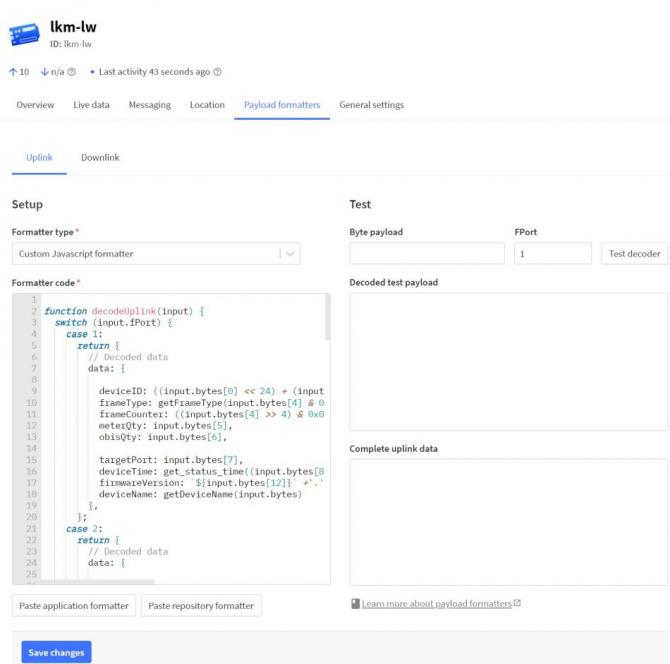
Use the decoder below for firmware v2.7.0 and later. The example targets The Things Network (TTN) / ChirpStack V3 payload formatters. In the common header, byte 4 carries the message type in its lower 4 bits (0x00 = Status, 0x01 = OBIS Codes, 0x02 = Meter Response) and the package number in its upper 4 bits, which is incremented for each split package (see Chapter 13.7).
Note: Meter Response values are sent as scaled 32-bit integers (the decimal separator is removed); the decimal position is defined by each OBIS code and must be applied on the application side. Byte order follows the gateway “Word Swap” setting (default OFF = big-endian).
/**
 * REDZ LKM Series - LoRaWAN Uplink Payload Formatter (Decoder)
 * Firmware: v2.7.0 and later
 *
 * Common header (all uplinks): 4-byte Device ID (big-endian) + 1-byte Message Type.
 *   Message Type: 0x00 = Status, 0x01 = OBIS Codes, 0x02 = Meter Response.
 *
 * NOTE on Meter Response values: the gateway strips the decimal separator and
 * sends each reading as a scaled 32-bit integer (NOT a float). The decimal
 * position is defined by the OBIS code, not by the payload. Word order follows
 * the gateway "Word Swap" setting (default OFF = big-endian).
 */

// OBIS profile index (0..5) as shown on the OBIS code profile tabs.
var PROFILE_NAMES = [
  "IEC 62056-21",    // 0
  "Landis+Gyr DLMS", // 1
  "Actaris/Itron",   // 2
  "Iskra DLMS",      // 3
  "Cewe DLMS",       // 4
  "Generic DLMS"     // 5
];

function decodeUplink(input) {
  var b = input.bytes;
  var warnings = [];

  if (b.length < 5) {
    return { data: {}, warnings: warnings, errors: ["payload too short (min 5 bytes)"] };
  }

  // ---- Common header ----
  var deviceId = ((b[0] << 24) | (b[1] << 16) | (b[2] << 8) | b[3]) >>> 0;
  var messageType = b[4] & 0x0F;          // message type: lower 4 bits
  var packageNumber = (b[4] >> 4) & 0x0F; // package number: upper 4 bits

  var data = {
    deviceId: deviceId,
    deviceIdHex: toHex32(deviceId),
    packageNumber: packageNumber
  };

  // Set true if the gateway "Word Swap" option is enabled.
  var WORD_SWAP = false;

  if (messageType === 0x00) {
    // ---------- Status message (fPort 1) ----------
    data.messageType = "status";
    if (b.length < 20) {
      return { data: data, warnings: warnings, errors: ["status payload too short (min 20 bytes)"] };
    }
    data.meterCount = b[5];

    // 6 OBIS-count bytes, one per profile (indices 0..5)
    var obisPerProfile = [];
    for (var p = 0; p < 6; p++) {
      obisPerProfile.push({
        profile: p,
        profileName: PROFILE_NAMES[p] || ("profile " + p),
        obisCount: b[6 + p]
      });
    }
    data.obisPerProfile = obisPerProfile;

    data.loRaWANPort = b[12];

    // 4-byte RTC time (big-endian); see decodeRtcTime() for the packed field layout
    var rtc = ((b[13] << 24) | (b[14] << 16) | (b[15] << 8) | b[16]) >>> 0;
    data.deviceTime = decodeRtcTime(rtc);

    data.firmwareVersion = b[17] + "." + b[18] + "." + b[19];

    // Remaining bytes = device name (ASCII, up to 22 chars)
    var name = "";
    for (var n = 20; n < b.length; n++) {
      if (b[n] === 0) break;
      name += String.fromCharCode(b[n]);
    }
    data.deviceName = name;

  } else if (messageType === 0x01) {
    // ---------- OBIS Codes message (fPort 2) ----------
    data.messageType = "obisCodes";
    var entries = [];
    var i = 5;
    while (i + 8 <= b.length) {
      var profile = b[i];
      var obisIndex = b[i + 1]; // 1-based index within the profile
      var obisCode = b[i + 2] + "." + b[i + 3] + "." + b[i + 4] + "." +
                     b[i + 5] + "." + b[i + 6] + "." + b[i + 7];
      entries.push({
        profile: profile,
        profileName: PROFILE_NAMES[profile] || ("profile " + profile),
        obisIndex: obisIndex,
        obisCode: obisCode
      });
      i += 8;
    }
    if (i !== b.length) {
      warnings.push("trailing bytes ignored (OBIS records are 8 bytes each)");
    }
    data.obisCount = entries.length;
    data.obisCodes = entries;

  } else if (messageType === 0x02) {
    // ---------- Meter Response message (fPort = configured data port) ----------
    data.messageType = "meterResponse";
    if (b.length < 8) {
      return { data: data, warnings: warnings, errors: ["meter response too short (min 8 bytes)"] };
    }
    data.meterNumber = b[5];      // 1-based meter index
    data.firstObisIndex = b[6];   // 1-based index of first enabled OBIS
    var dataSize = b[7];          // number of data bytes that follow

    var available = b.length - 8;
    if (dataSize > available) {
      warnings.push("declared data size (" + dataSize + ") exceeds payload (" + available + ")");
      dataSize = available;
    }

    // Each value = 4 bytes (2 Modbus registers) = one scaled int32 reading
    var values = [];
    for (var d = 8; d + 4 <= 8 + dataSize; d += 4) {
      var raw;
      if (WORD_SWAP) {
        // low register first: [b1 b0 b3 b2]
        raw = ((b[d + 2] << 24) | (b[d + 3] << 16) | (b[d] << 8) | b[d + 1]);
      } else {
        // high register first (big-endian int32): [b3 b2 b1 b0]
        raw = ((b[d] << 24) | (b[d + 1] << 16) | (b[d + 2] << 8) | b[d + 3]);
      }
      // raw is a signed 32-bit integer (the | operator sign-extends)
      values.push(raw);
    }
    data.valueCount = values.length;
    // Scaled integers: apply the decimal scaler defined by each OBIS code.
    data.values = values;

  } else {
    return { data: data, warnings: warnings, errors: ["unknown message type 0x" + messageType.toString(16)] };
  }

  return { data: data, warnings: warnings, errors: [] };
}

// ---- Helpers ----
function toHex32(v) {
  var s = (v >>> 0).toString(16).toUpperCase();
  while (s.length < 8) s = "0" + s;
  return "0x" + s;
}

// Gateway RTC packed u32 (firmware RTC_MAKE_DATETIME_U32):
//   sec[5:0] min[11:6] month[15:12] hour[20:16] day[25:21] year[31:26] (year offset from 2000)
function decodeRtcTime(v) {
  var sec   =  v         & 0x3F;
  var min   = (v >>> 6)  & 0x3F;
  var month = (v >>> 12) & 0x0F;
  var hour  = (v >>> 16) & 0x1F;
  var day   = (v >>> 21) & 0x1F;
  var year  = 2000 + ((v >>> 26) & 0x3F);
  return pad(day) + "-" + pad(month) + "-" + year + " " +
         pad(hour) + ":" + pad(min) + ":" + pad(sec);
}
function pad(n) { return (n < 10 ? "0" : "") + n; }
LKM Series Electricity Meter Protocol to Modbus Protocol Gateways with MQTT can read up to 32 meters on RS485 Bus and RS232 and converts up to 48 OBIS codes to Modbus registers for each meter in reading list. In this example we will read 1 meter via direct cable connection over RS485 and other meter over KMK114- RS485 optical interface.
NOTE: Lite models read up to 10 meters and only support RS485 serial connection.
Direct Connected to Meter Models can read the meter it is connected only and have no RS232 or RS485 port at all.
LKM Series Electricity Meter Protocol to Modbus Protocol Gateways with MQTT can be connected to RS485 or RS232 of meter and read the IEC 62056-21 (Mode C) or DLMS/COSEM protocol. Remote or local Data Acquisition Server can read meter data via Modbus TCP.
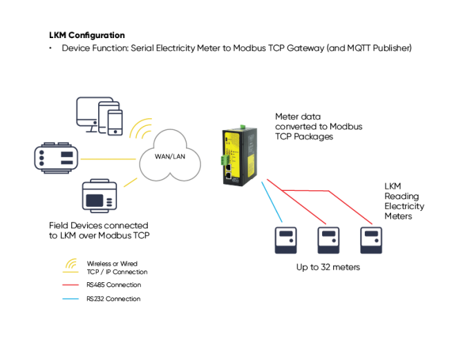
LKM Series Electricity Meter Protocol to Modbus Protocol Gateways with MQTT can be connected to optical interface of meter and read the IEC 62056-21 (Mode C) protocol with auto baud change, or DLMS/COSEM using the "DLMS/COSEM with IEC62056-21 Opening" protocol option. Remote or local Data Acquisition Server can read meter data via Modbus TCP.
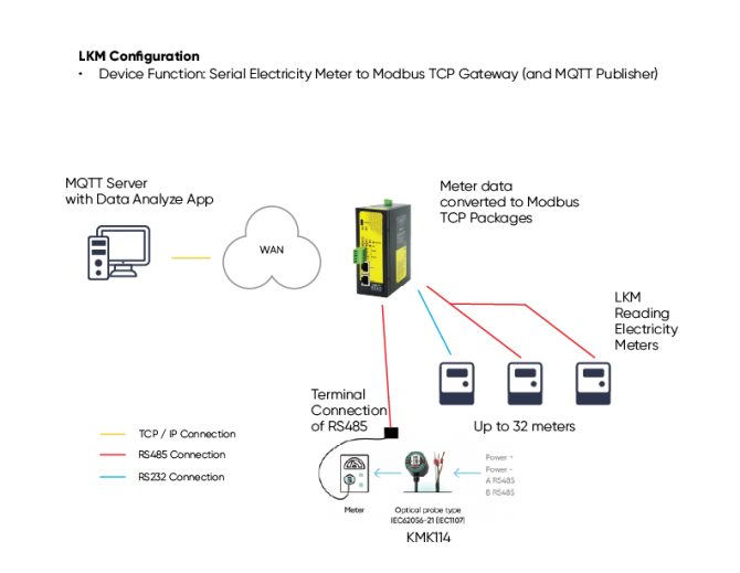
Here is an example video taken from PC screen
Here is an example video physical application
Here is an example video taken from PC screen
Here is an example video physical application
LKM154: Electricity Meter Protocol to Modbus Protocol Gateway with MQTT, 2 x 10/100 T(x) ETH ports, 1 x RS232 & 1 x RS485, 5-48V (max. 60V) DC Power Input
LKM254: Electricity Meter Protocol to Modbus Protocol Gateway with MQTT, 2 x 10/100 T(x) ETH ports, 1 x RS232 & 1 x RS485, 100 - 240V AC (120 – 370V DC), 50Hz to 60Hz AC Power Input
LKM655: Electricity Meter Protocol to Modbus Protocol Gateway with MQTT, 2 x 10/100 T(x) ETH ports + 1 x BPL (Broadband Power Line) Link, 1 x RS232 & 1 x RS485, 3 Phase AC Power Input, 110V–240V/50-60Hz
LKM154 - Lite: Electricity Meter Protocol to Modbus Protocol Gateway with MQTT, 1 x 10/100 T(x) ETH port and 1 x RS485, 9-36V (max. 40V) DC Power Input
LKM354: 868MHz LoRaWAN Meter Reader and Electricity Meter Protocol to Modbus Protocol Gateway with MQTT, 2 x 10/100 T(x) ETH ports, 1 x RS232 & 1 x RS485, 5-48V (max. 60V) DC Power Input
LKM454: 868MHz LoRaWAN Meter Reader and Electricity Meter Protocol to Modbus Protocol Gateway with MQTT, 2 x 10/100 T(x) ETH ports, 1 x RS232 & 1 x RS485, 100 - 240V AC (120 – 370V DC), 50Hz to 60Hz AC Power Input
LKM755: 868MHz LoRaWAN Meter Reader and Electricity Meter Protocol to Modbus Protocol Gateway with MQTT, 2 x 10/100 T(x) ETH ports + 1 x BPL (Broadband Power Line) Link, 1 x RS232 & 1 x RS485, 3 Phase AC Power Input, 110V–240V/50-60Hz
LKM354 - Lite: 868MHz LoRaWAN Meter Reader and Electricity Meter Protocol to Modbus Protocol Gateway with MQTT, 1 x 10/100 T(x) ETH port and 1 x RS485, 9-36V (max. 40V) DC Power Input
LKM615: Electricity Meter Protocol to Modbus Protocol Gateway with MQTT, 1x 10/100 T(x) ETH port, Meter Side is Direct Connection to Meter, Powered from Meter Interface
LKM616: 868MHz LoRaWAN Meter Reader and Electricity Meter Protocol to Modbus Protocol Gateway with MQTT, 1x 10/100 T(x) ETH port, Meter Side is Direct Connection to Meter, Powered from Meter Interface
NOTE: LKM series has also Modbus RTU versions:
LKM111, LKM114, LKM124, LKM141, LKM144 and LKM614
check those models please if Modbus RTU version is needed in the project.
| Model | 868MHz LoRaWAN Meter Reader | Gets Power From Meter Directly (Isolated) | 9-36V (max. 40V) DC Power Input | 5-48V (max. 60V) DC Power Input | 100 - 240V AC (120 – 370V DC), 50Hz to 60Hz AC Power Input | 3 Phase AC Power input, 110 V – 240 V / 50 – 60 Hz AC Power Input | Directly Connects to Meter. Read 1 Meter and, Convert Data to Modbus and/or Send to MQTT | Read Up to 10 Meters and Convert Data to Modbus and/or send to MQTT Server | Read Up to 32 Meters and Convert Data to Modbus and/or send to MQTT Server | OBIS Codes to look for can be changed by user | Web Interface for monitoring meter reading status and much more | BPL (Broadband Power Line) Link |
| LKM154 | X |
X |
X | X | ||||||||
| LKM254 | X | X | X | X | ||||||||
| LKM655 | X |
X | X | X | X | |||||||
| LKM154 - Lite | X | X | X | X | ||||||||
| LKM354 |
X |
X | X |
X |
X |
|||||||
| LKM454 |
X | X |
X |
X |
X |
|||||||
| LKM755 |
X | X |
X |
X |
X |
X |
||||||
| LKM354 - Lite | X | X | X | X | X | |||||||
| LKM615 | X | X | X | X | ||||||||
| LKM616 | X | X | X | X | X |
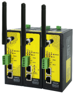
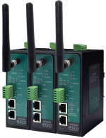
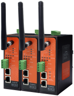
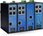
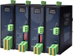
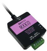
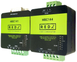


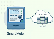
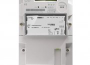



THIS SITE USES COOKIES
Various types of cookies are used on our website (and on all other
digital platforms including mobile applications).
View our new THE INFORMATIVE TEXT ON LPPD AND PRIVACY here.
Google Analytics
Analytical cookies help us to improve our website by collecting and
reporting information on its usage.
Google AdWords and Remarketing
We use marketing cookies to help us improve the relevancy of advertising
campaigns you receive.
I have read the above articles
 download