Various types of cookies are used on our website (and on all other digital platforms including mobile applications). View our new THE INFORMATIVE TEXT ON LPPD AND PRIVACY here. Google Analytics Analytical cookies help us to improve our website by collecting and reporting information on its usage. Google AdWords ve Remarketing We use marketing cookies to help us improve the relevancy of advertising campaigns you receive.
I have read the above articles
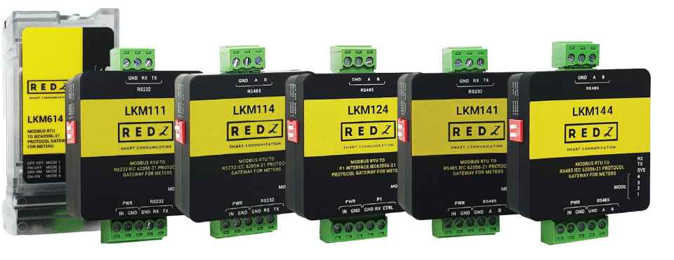
LKM Series Modbus to IEC62056-21 and P1 Companion Standard Protocol Gateways are designed to be used with electricity meters that communicate in IEC62056-21 or P1 Companion Standard. The meters that support those protocols has read out tables that has several data such as import energy, export energy, phase voltages and currents. LKM Series Protocol Gateway automatically reads those values and maps to Modbus registers. Field devices or software systems can easily read data over Modbus RTU or TCP protocol so that energy meter reading can easily be integrated to field automation or monitoring systems without need of IEC6056-21 or P1 Companion Standard implementation.
LKM series Modbus RTU gateways can read meters with auto baud changes or fixed baud rates and supports up to 10 meters on RS485 bus.
LKM614 is especially designed for EMH LZQJ-XC meters and it is direct replacement for Variomod XC modules.
LKM Series Electricity Meter Protocol to Modbus RTU Protocol Gateways support 2-way communication. One side connected directly or via optical probe to read electricity meter with IEC62056-21 protocol or P1 Companion Standard, other side can be connected to a field device such as PLC or RTU or serial device server connected to an automation software system that can read Modbus RTU devices.
There are standalone versions and also plug and play version for EMH LZQJ-XC meters.
Also there are Modbus RTU and Modbus TCP versions with MQTT connectivity and LoRaWAN Connectivity..
LKM Series Electricity Meter Protocol to Modbus RTU Protocol Gateways built in a very small form factor.
Standalone versions are only 2.1 x 4.2 x 4.4cm. Thus, it can be acted as part of cable and no need special mounting. Simply connect cables and use as a part of cable.

Plug and Play version can directly fit into EMH LZQJ-XC meter. It is direct replacement for Variomod XC modules. Simply plug in LKM614 into meter.
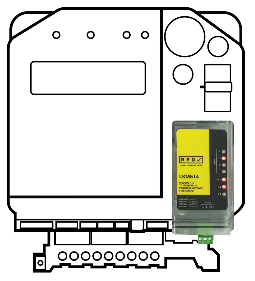
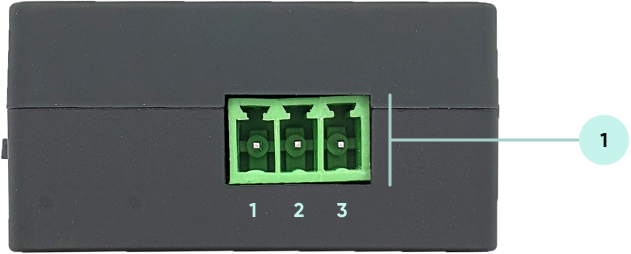
| Pin Number | Description |
| 1 | GND |
| 2 | Rx |
| 3 | Tx |
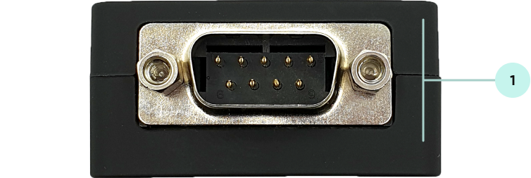
| Pin Number | Description |
| 1 | Not Used |
| 2 | Rx |
| 3 | Tx |
| 4 | Not Used |
| 5 | GND |
| 6 | Not Used |
| 7 | Not Used |
| 8 | Not Used |
| 9 | Not Used |

| Pin Number | Description |
| 1 | GND |
| 2 | A |
| 3 | B |
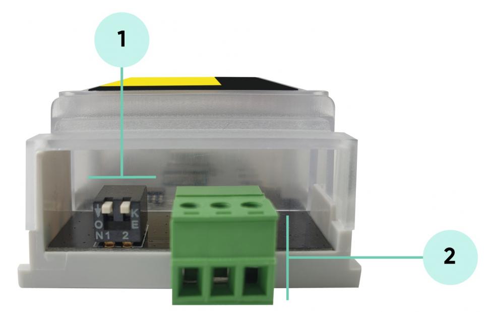
| Pin Positions (1-2) | LED Status | Modem Side Communication Data Type | Meter Side Communication |
| OFF-OFF | Mode 1 LED ON | 19200 8N1 | Starts with 300 baud rate and changes during transmission to target baud rate based on IEC62056-21 protocol |
| ON-OFF | Mode 2 LED ON | 9600 8N1 | Starts with 300 baud rate and changes during transmission to target baud rate based on IEC62056-21 protocol |
| OFF-ON | Mode 3 LED ON | 19200 8N1 | 19200 7E1 Fixed |
| ON-ON | Mode 4 LED ON | 9600 8N1 | 9600 7E1 Fixed |

NOTE: After changing operating mode of device, device must be repowered to apply new setting. Which means device must be plugged out of the device and plugged in back again.
| Pin Number | Description |
| 1 | A |
| 2 | B |
| 3 | GND |
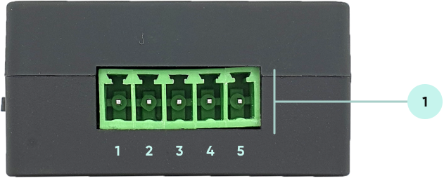
| Pin Number | Description |
| 1 |
Input Power + (5V - 24V DC) |
| 2 |
Input Power - GND |
| 3 | GND |
| 4 | Rx |
| 5 | Tx |

NOTE: Power Input has polarity protection. Yet again please check polarity when connecting multiple devices in same power source, otherwise device may burn due to wrong connection of power.

| Pin Number | Description |
| 1 |
Input Power + (5V - 24V DC) |
| 2 |
Input Power - GND |
| 3 | GND |
| 4 | Rx (Data) |
| 5 | CTRL (Data Request) |
User should arrange RJ12 cable needed to connect to meter in desired length.
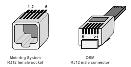
| Pin Number | Description |
| 1 |
+5V Power Supply |
| 2 |
Data Request (CTRL) |
| 3 | Data GND |
| 4 | Not connected (NC) |
| 5 | Data (Rx) |
| 6 | Power GND |

NOTE: Power Input has polarity protection. Yet again please check polarity when connecting multiple devices in same power source, otherwise device may burn due to wrong connection of power.

| Pin Number | Description |
| 1 |
Input Power + (5V - 24V DC) |
| 2 |
Input Power - GND |
| 3 | GND |
| 4 | A |
| 5 | B |

NOTE: Power Input has polarity protection. Yet again please check polarity when connecting multiple devices in same power source, otherwise device may burn due to wrong connection of power.
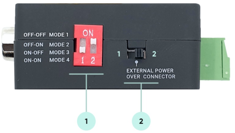
| Pin Positions (1-2) | LED Status | Modem Side Communication Data Type | Meter Side Communication |
| OFF-OFF | Mode 1 LED ON | 19200 8N1 | Starts with 300 baud rate and changes during transmission to target baud rate based on IEC62056-21 protocol |
| OFF-ON | Mode 2 LED ON | 9600 8N1 | Starts with 300 baud rate and changes during transmission to target baud rate based on IEC62056-21 protocol |
| ON-OFF | Mode 3 LED ON | 19200 8N1 | 19200 7E1 Fixed |
| ON-ON | Mode 4 LED ON | 9600 8N1 | 9600 7E1 Fixed |

NOTE: After changing operating mode of device, device must be repowered to apply new setting.
| Switch Position | Description |
| 1 | Power Off Device |
| 2 | Power On Device |
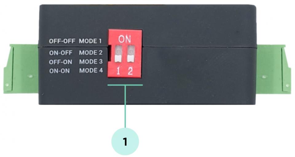
(can be different depending on customer specific firmware)
| Pin Positions (1-2) | LED Status | Modem Side Communication Data Type | Meter Side Communication |
| OFF-OFF | Mode 1 LED ON | 19200 8N1 | Starts with 300 baud rate and changes during transmission to target baud rate based on IEC62056-21 protocol |
| ON-OFF | Mode 2 LED ON | 9600 8N1 | Starts with 300 baud rate and changes during transmission to target baud rate based on IEC62056-21 protocol |
| OFF-ON | Mode 3 LED ON | 19200 8N1 | 19200 7E1 Fixed |
| ON-ON | Mode 4 LED ON | 9600 8N1 | 9600 7E1 Fixed |

NOTE: After changing operating mode of device, device must be repowered to apply new setting.

(can be different depending on customer specific firmware)
| Pin Positions (1-2) | LED Status | Modem Side Communication Data Type | Meter Side Communication |
| OFF-OFF | Mode 1 LED ON | 9600 8N1 | 9600 8N1 Fixed |
| ON-OFF | Mode 2 LED ON | 19200 8N1 | 19200 8N1 Fixed |
| OFF-ON | Mode 3 LED ON | 57600 8N1 | 57600 8N1 Fixed |
| ON-ON | Mode 4 LED ON | 115200 8N1 | 115200 8N1 Fixed |

NOTE: After changing operating mode of device, device must be repowered to apply new setting.
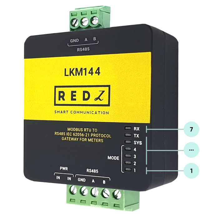
| LED Number | Description |
| 1 | Mode 1 LED |
| 2 | Mode 2 LED |
| 3 | Mode 3 LED |
| 4 | Mode 4 LED |
| 5 | System LED: Blinks every second |
| 6 | Tx LED: Sending data from Modem Side to Meter Side |
| 7 | Rx LED: Receiving data from Meter Side to Modem Side |
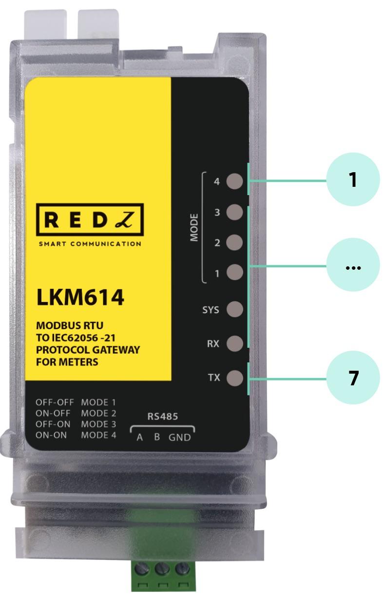
| LED Number | Description |
| 1 | Mode 4 LED |
| 2 | Mode 3 LED |
| 3 | Mode 2 LED |
| 4 | Mode 1 LED |
| 5 | System LED: Blinks every second |
| 6 | Rx LED: Receiving data from Meter |
| 7 | Tx LED: Sending data to Meter |
LKM Series Electricity Meter Protocol to Modbus RTU Protocol Gateways can be used in different scenarios. Usages are not limited to that examples and user may create their own usage scenario.
LKM Series Electricity Meter Protocol to Modbus RTU Protocol Gateways standalone versions support up to 10 meters reading on RS485 Bus.
LKM Series Modbus TCP with MQTT Connectivity ( and LoRaWAN Connectivity) standalone versions support up to 20 meters reading on RS485 Bus and RS232.
LKM Series Electricity Meter Protocol to Modbus RTU Protocol Gateways can be connected to RS485 or P1 serial line of meter and can operate in fixed baud rate mode. Other side of device can be connected to remote Data Acquisition Server via TCP/IP device that can convert Modbus TCP to Modbus RTU.
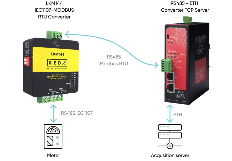
LKM Series Electricity Meter Protocol to Modbus RTU Protocol Gateways can be connected to optical probe of meter via REDZ KMK series optical probes and can operate in changing baud rate mode. Other side of device can be connected to remote Data Acquisition Server via TCP/IP device that can convert Modbus TCP to Modbus RTU.
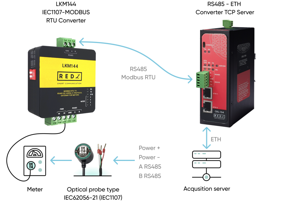
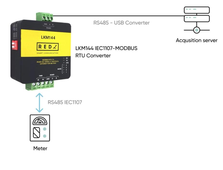
LKM Series Electricity Meter Protocol to Modbus RTU Protocol Gateways can be connected to RS485 or P1 serial line of meter and can operate in fixed baud rate mode. Other side of device can be connected to Data Acquisition Server via Cable connection as well and server can read data with Modbus RTU protocol.
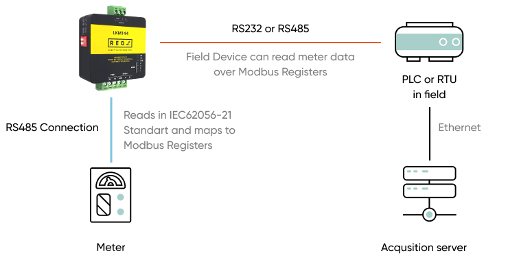
LKM Series Electricity Meter Protocol to Modbus RTU Protocol Gateways can be connected to RS485 or P1 serial line of meter and can operate in fixed baud rate mode. Other side of device can be connected to a field device such as PLC or RTU and that device can read data with Modbus RTU protocol.
LKM614 Electricity Meter Protocol to Modbus RTU Protocol Gateway is especially designed for EMH LZQJ-XC meters and it is direct replacement for Variomod XC modules. LKM614 can be connected to EMH LZQJ-SC meter in fixed baud rate or auto baud rate mode based on meter settings. Other side of device can be connected to a field device such as PLC or RTU and that device can read data with Modbus RTU protocol. If needed, that device can also be connected to REDZ CKL series Modbus TCP – RTU Converter to read Modbus values over LAN or WAN.
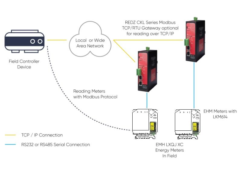
LKM Series Electricity Meter Protocol to Modbus RTU Protocol Gateways’ one side should be connected directly or via optical probe to read electricity meter and other side should be connected to a field device such as PLC or RTU or serial device server connected to an automation software system that can read Modbus RTU devices.
LKM Series Electricity Meter Protocol to Modbus RTU Protocol Gateways read the data table of electricity meters and maps the data in following Modbus Registers:
| Register Number | OBIS Code | Search String | Register Name | Modbus Address (Dec) | Modbus Address (Hex) | Data Type |
| 1 | 0.9.1 | “0.9.1” | Time | 1 | 0x01 | Unsigned Long (UInt32) |
| 2 | 0.9.2 | “0.9.2” | Date | 3 | 0x03 | Unsigned Long (UInt32) |
| 3 | 1.8.0 | "1.8.0" | Total active energy import A+ | 5 | 0x05 | Unsigned Long (UInt32) |
| 4 | 2.8.0 | "2.8.0" | Total active energy export A- | 7 | 0x07 | Unsigned Long (UInt32) |
| 5 | 3.8.0 | "3.8.0" | Total reactive energy R+ | 9 | 0x09 | Unsigned Long (UInt32) |
| 6 | 4.8.0 | "4.8.0" | Total reactive energy R- | 11 | 0x0B | Unsigned Long (UInt32) |
| 7 | 5.8.0 | "5.8.0" | Total reactive inductive energy import (Ri+) Q1 | 13 | 0x0D | Unsigned Long (UInt32) |
| 8 | 6.8.0 | "6.8.0" | Total reactive capacitive energy import (Rc+) Q2 | 15 | 0x0F | Unsigned Long (UInt32) |
| 9 | 7.8.0 | "7.8.0" | Total reactive inductive energy export (Ri-) Q3 | 17 | 0x11 | Unsigned Long (UInt32) |
| 10 | 8.8.0 | "8.8.0" | Total reactive capacitive energy export (Rc-) Q4 | 19 | 0x13 | Unsigned Long (UInt32) |
| 11 | 1.6.0 | "1.6.0" | Total maximal average import power P+max | 21 | 0x15 | Unsigned Long (UInt32) |
| 12 | 2.6.0 | "2.6.0" | Total maximal average export power P-max | 23 | 0x17 | Unsigned Long (UInt32) |
| 13 | 1.5.0 | "1.5.0" | Total average import power P+max (last period value) | 25 | 0x19 | Unsigned Long (UInt32) |
| 14 | 1.7.0 | "1.7.0" | Total instantaneous value power P+ | 27 | 0x1B | Unsigned Long (UInt32) |
| 15 | 31.7.0 | “31.7.0” | L1 Current ; instantaneous value | 29 | 0x1D | Unsigned Long (UInt32) |
| 16 | 51.7.0 | “51.7.0” | L2 Current ; instantaneous value | 31 | 0x1F | Unsigned Long (UInt32) |
| 17 | 71.7.0 | “71.7.0” | L3 Current ; instantaneous value | 33 | 0x21 | Unsigned Long (UInt32) |
| 18 | 32.7.0 | “32.7.0” | L1 Voltage; instantaneous value | 35 | 0x23 | Unsigned Long (UInt32) |
| 19 | 52.7.0 | “52.7.0” | L2 Voltage; instantaneous value | 37 | 0x25 | Unsigned Long (UInt32) |
| 20 | 72.7.0 | “72.7.0” | L3 Voltage; instantaneous value | 39 | 0x27 | Unsigned Long (UInt32) |
| 21 | 13.7.0 | “13.7.0” | Power factor | 41 | 0x29 | Unsigned Long (UInt32) |
| 22 | 14.7.0 | “14.7.0” | Frequency | 43 | 0x2B | Unsigned Long (UInt32) |
| 23 | C.1.0 | “C.1.0” | Meter number / meter ID | 45 | 0x2D | Unsigned Long (UInt32) |
| 24 | 16.7.0 | “16.7.0” | Sum active instantaneous power (A+ - A-) | 47 | 0x2F | Unsigned Long (UInt32) |
The search strings are defined in firmware of device and can be customized based on customer’s project. LKM Series Electricity Meter Protocol to Modbus RTU Protocol Gateways read the read-out table (table number can be configured by user with Modbus command. See relevant section to configure) of IEC62056-21 or P1 Companion Standard meter and searches the strings and maps the values of first occurrence to Modbus register address. If the data is unavailable LKM will store zero “0” as value.
LKM Series Electricity Meter Protocol to Modbus RTU Protocol Gateways alternatively read the data table of IEC62056-21 or P1 Companion Standard meter and maps the data in following Modbus Registers:

NOTE: Those are available alternatives and they are not limited to given examples.
|
OBIS name for firmware |
Searched OBIS Codes |
|
OBIS_EURO
|
"0.9.1", "0.9.2", "1.8.0", "2.8.0", "3.8.0", "4.8.0", "5.8.0", "6.8.0", "7.8.0", "8.8.0", "1.6.0", "2.6.0",
"1.5.0", "1.7.0", "31.7.0", "51.7.0", "71.7.0", "32.7.0", "52.7.0", "72.7.0", "13.7.0", "14.7.0", "C.1.0", "16.7.0" |
|
OBIS_EURO_1
|
"0.9.1", "0.9.2", "1.8.0", "2.8.0", "3.8.0", "4.8.0", "5.8.0", "6.8.0", "7.8.0", "8.8.0", "1.6.0", "2.6.0",
"2.7.0", "1.7.0", "31.7", "51.7", "71.7", "32.7", "52.7", "72.7", "13.7", "14.7", "C.1.0", "C.7.0" |
|
OBIS_EURO_2
|
"0.9.1", "0.9.2", "1.8.0", "2.8.0", "3.8.0", "4.8.0", "5.8.0", "6.8.0", "7.8.0", "8.8.0", "32.25", "52.25",
"72.25", "31.25", "51.25", "71.25", "1.25", "3.25", "13.25", "33.25", "53.25", "73.25", "9.25", "14.25" |
|
OBIS_EURO_3
|
"0.9.1", "0.9.2", "1.8.0", "2.8.0", "3.8.0", "4.8.0", "5.8.0", "6.8.0", "7.8.0", "8.8.0", "32.25", "52.25",
"1.0.0", "1.7.0", "2.7.0", "3.7.0", "4.7.0", "32.7.0", "31.7.0", "33.25", "53.25", "73.25", "9.25", "14.25" |
|
OBIS_EURO_4
|
"0.9.1","0.9.2", "1.8.0", "2.8.0", "3.8.0","4.8.0", "5.8.0", "6.8.0", "7.8.0","8.8.0", "1.6.1", "2.6.1",
"1.6.1*","2.6.1*", "1.8.0*", "2.8.0*", "3.8.0*","4.8.0*", "5.8.0*", "6.8.0*", "7.8.0*","8.8.0*", "C.86.0", "C.7.0" |
|
OBIS_EURO_5
|
"1.8.0", "2.8.0", "5.8.0", "6.8.0", "7.8.0", "8.8.0", "9.8.0", "10.8.0", "1.7.0", "2.7.0", "3.7.0", "4.7.0",
"31.7.0", "51.7.0", "71.7.0", "32.7.0", "52.7.0", "72.7.0", "1.8.1", "1.8.2", "5.8.1", "5.8.2", "8.8.1", "8.8.2" |
|
OBIS_EURO_6
|
"0.9.1","0.9.2", "1.8.0", "2.8.0", "1.4.0","2.4.0", "5.8.0", "6.8.0", "7.8.0","8.8.0", "1.6.0", "2.6.0",
"1.5.0", "2.5.0", "31.7.0", "51.7.0", "71.7.0","32.7.0", "52.7.0", "72.7.0", "13.7.0","14.7.0", "C.1.0", "16.7.0" |
|
OBIS_EURO_7
|
"1.6.0", "0.0.0", "0.0.2", "1.8.0", "2.8.0", "0.9.1", "0.9.2", "21.25", "41.25", "61.25", "1.25", "31.25",
"51.25", "71.25", "32.25", "52.25", "72.25", "33.25", "53.25", "73.25", "13.25", "14.25", "C.52.0", "C.86.0" |
|
OBIS_EURO_8
|
"0.9.1", "0.9.2", "1.8.0", "2.8.0", "3.8.0", "4.8.0", "1.9.1", "1.9.2", "1.9.3", "8.8.0", "1.6.1", "2.6.1",
"1.7", "2.7", "31.7", "51.7", "71.7", "32.7", "52.7", "72.7", "13.7", "14.7", "3.7", "4.7" |
|
OBIS_EURO_9
|
"1.25", "3.25", "9.25", "31.25", "51.25", "71.25", "32.25", "52.25", "72.25", "13.25", "14.25", "1.8.0",
"1.8.1", "1.8.2", "2.8.0", "2.8.1", "2.8.2", "3.8.0", "3.8.1", "3.8.2", "4.8.0", "4.8.1", "4.8.2", "9.8.0" |
|
OBIS_EURO_10
|
"0.9.1", "0.9.2", "1.25", "9.25", "31.25", "51.25", "71.25", "32.25", "52.25", "72.25", "81.7.40", "81.7.51",
"81.7.62", "33.25", "53.25", "73.25", "13.25", "14.25", "1.8.0", "2.8.0", "5.8.0", "6.8.0", "7.8.0", "8.8.0" |
|
OBIS_EURO_11 |
"0.9.1*", "0.9.2*", "0.2.0*", "C.1.0*", "C.1.6*", "C.51.1*", "C.51.2*", "C.51.3*", "C.51.4*", "C.51.5*", "C.51.6*", "C.51.7*",
"C.51.8*", "C.6.0*", "C.6.1*", "1.8.0*", "2.8.0*", "F.F.0*", "3.8.0*", "4.8.0*", "5.8.0*", "6.8.0*", "7.8.0*", "8.8.0*" |
|
OBIS_EURO_12 |
"0.0.1", "C.1.0", "0.9.1", "0.9.2", "14.25", "1.25", "3.25", "9.25", "13.25", "21.25", "23.25", "29.25",
"31.25", "32.25", "41.25", "43.25", "49.25", "51.25", "52.25", "61.25", "63.25", "69.25", "71.25", "72.25" |
|
OBIS_EURO_13 |
"0.9.1", "0.9.2", "1.8.0", "2.8.0", "3.8.0", "4.8.0", "5.8.0", "6.8.0", "7.8.0", "8.8.0", "1.6.0", "2.6.0",
"1.5.0", "1.7.0", "1.8.1", "1.8.2", "1.8.3", "2.8.1", "2.8.2", "2.8.3", "13.7", "14.7", "C.1.0", "C.7.0" |
|
OBIS_EURO_14 |
"1.8.0", "2.8.0", "9.8.0", "10.8.0", "3.8.0", "4.8.0", "32.7.0", "52.7.0", "72.7.0", "14.7", "13.7", "33.7",
"53.7", "73.7", "16.7.0", "36.7.0", "56.7.0", "76.7.0", "131.7.0", "9.7.0", "29.7.0", "49.7.0", "69.7.0", "31.7.0" |
|
OBIS_EURO_15 |
"0.9.1", "0.9.2", "21.25", "41.25", "61.25", "1.25", "3.25", "9.25", "31.25", "51.25", "71.25", "32.25",
"52.25", "72.25", "81.7.40", "81.7.51", "81.7.62", "14.25", "1.8.0", "2.8.0", "5.8.0", "6.8.0", "7.8.0", "8.8.0" |
|
OBIS_EURO_16 |
"0.9.1", "0.9.2", "1.8.0", "2.8.0", "3.8.0", "4.8.0", "5.8.0", "6.8.0", "7.8.0", "8.8.0", "1.6.1", "2.6.1",
"2.7.0", "1.25", "31.25", "51.25", "71.25", "32.25", "52.25", "72.25", "13.25", "14.25", "9.25", "C.1.0" |
|
OBIS_EURO_17 |
"F.F", "0.9.1", "0.9.2", "C.1.0", "16.7.0", "131.7.0", "9.7.0", "1.8.1", "1.8.2", "1.8.3", "1.8.0", "2.8.1",
"2.8.2", "2.8.3", "2.8.0", "5.8.1", "5.8.2", "5.8.3", "5.8.0", "8.8.1", "8.8.2", "8.8.3", "8.8.0", "1.6.0" |
|
OBIS_EURO_18 |
"21.25", "41.25", "61.25", "1.25", "3.25", "9.25", "31.25", "51.25", "71.25", "32.25", "52.25", "72.25",
"33.25", "53.25", "73.25", "13.25", "14.25", "1.8.0", "2.8.0", "3.8.0", "4.8.0", "9.8.0", "10.8.0", "1.6.0" |
|
OBIS_EURO_19 |
"F.F", "0.0.0", "0.1.0", "0.1.2*", "1.8.1", "1.8.1*", "2.8.1", "2.8.1*", "3.8.1", "3.8.1*", "4.8.1", "4.8.1*",
"1.6.1", "1.6.1*", "2.6.1", "2.6.1*", "3.6.1", "3.6.1*", "4.6.1", "4.6.1*",
"0.9.1", "0.9.2", "0.4.2", "0.4.3" |
|
OBIS_EURO_TRF
|
"0.9.1", "0.9.2", "1.8.0", "2.8.0", "3.8.0", "4.8.0", "5.8.0", "6.8.0", "7.8.0", "8.8.0", "1.6.0", "2.6.0",
"1.5.0", "1.7.0", "1.8.1", "1.8.2", "1.8.3", "2.8.1", "2.8.2", "2.8.3", "13.7","14.7", "C.1.0", "C.7.0" |
|
OBIS_EURO_TRF_2 |
"F.F.0", "0.9.1", "0.9.2" , "0.0.0", "C.90.1", "C.1.0", "0.1.2", "0.1.3", "1.8.0", "1.8.1", "1.8.2", "1.8.3",
"2.8.0", "2.8.1", "2.8.2", "2.8.3", "5.8.0", "5.8.1", "5.8.2", "5.8.3", "6.8.0", "6.8.1", "6.8.2", "6.8.3" |

NOTE: User can get readout table of its meter and share during order to have specific OBIS list for LKM series.
LKM series can read 24 registers of up to 10 meters in RS485 bus.
LKM Series Protocol Gateway alternatively reads 64 registers from the data table of IEC62056-21 or P1 Companion Standard meter and maps the data in following Modbus Registers:

NOTE: Those are available alternatives and they are not limited to given examples.
LKM series standard version can read 24 registers/meter of up to 10 meters on RS485 bus.
LKM series can also read 64 registers/meter of up to 4 meters in RS485 bus in this 64 register versions.
|
OBIS name for firmware |
Searched OBIS Codes |
|
OBIS_EURO_2
|
"1.8.0", "2.8.0", "3.8.0", "4.8.0",//4 "5.8.0", "6.8.0", "7.8.0", "8.8.0",//8 "1.6.0", "2.6.0", "3.6.0", "4.6.0",//12
"5.6.0", "6.6.0", "7.6.0", "8.6.0",//16 "1.4.0", "2.4.0", "3.4.0", "4.4.0",//20 "5.4.0", "6.4.0", "7.4.0", "8.4.0",//24
"1.5.0", "2.5.0", "3.5.0", "4.5.0",//28 "5.5.0", "6.5.0", "7.5.0", "8.5.0",//32 "1.7.0", "21.7.0", "41.7.0", "61.7.0",//36
"2.7.0", "22.7.0", "42.7.0", "62.7.0",//40 "16.7.0", "36.7.0", "56.7.0", "76.7.0",//44 "3.7.0", "23.7.0", "43.7.0", "63.7.0",//48
"4.7.0", "24.7.0", "44.7.0", "64.7.0",//52 "131.7.0", "151.7.0", "171.7.0", "191.7.0",//56 "11.7.0", "31.7.0", "51.7.0", "71.7.0",//60 "32.7.0", "52.7.0", "72.7.0", "5.38.0"//64 |
|
OBIS_EURO_3
|
"F.F", "0.9.1", "0.9.2", "0.0.0",//4 "131.7.0", "1.4.0", "2.4.0", "5.4.0",//8 "6.4.0","7.4.0", "8.4.0", "1.5.0",//12
"2.5.0", "5.5.0", "6.5.0", "7.5.0",//16 "8.5.0", "1.6.0", "2.6.0", "5.6.0",//20 "6.6.0", "7.6.0", "8.6.0", "1.8.1",//24
"1.8.2", "1.8.3", "2.8.1", "2.8.2",//28 "2.8.3", "5.8.1", "5.8.2", "5.8.3",//32 "6.8.1", "6.8.2", "6.8.3", "7.8.1",//36
"7.8.2", "7.8.3", "8.8.1", "8.8.2",//40 "8.8.3", "1.8.5", "1.8.0", "2.8.0",//44 "5.8.0", "6.8.0", "7.8.0", "8.8.0",//48
"9.8.0", "32.7.0", "52.7.0", "72.7.0",//52 "31.7.0", "51.7.0", "71.7.0", "91.7.0",//56 "14.7", "81.7.0", "81.7.1", "81.7.2",//60 "81.7.4", "81.7.5", "81.7.6", "16.7.0"//64 |
|
OBIS_EURO_4
|
"F.F.0", "0.9.1", "0.9.2" , "0.0.0", //4 "C.90.1", "1.8.0", "2.8.0", "3.8.0", //8 "4.8.0", "5.8.0", "6.8.0", "7.8.0", //12 "8.8.0", "1.6.0", "2.6.0", "3.6.0", //16
"4.6.0", "5.6.0", "6.6.0", "7.6.0", //20 "8.6.0", "1.4.0", "2.4.0", "5.4.0", //24 "6.4.0", "7.4.0", "8.4.0", "1.5.0", //28 "2.5.0", "5.5.0", "6.5.0", "7.5.0", //32
"8.5.0", "1.7.0", "21.7.0", "41.7.0", //36 "61.7.0", "2.7.0", "22.7.0", "42.7.0", //40 "62.7.0", "3.7.0", "4.7.0", "5.7.0", //44 "6.7.0", "7.7.0", "8.7.0", "16.7.0", //48
"36.7.0", "56.7.0", "76.7.0", "131.7.0", //52 "151.7.0", "171.7.0", "191.7.0", "11.7.0", //56 "31.7.0", "51.7.0", "71.7.0", "32.7.0", //60 "52.7.0", "72.7.0", "5.38.0", "13.7.0" //64 |
|
OBIS_EURO_5 |
"0.9.1", "0.9.2", "0.1.2*", "96.6.6",//4 "97.97.0", "97.98.1", "1.8.0", "2.8.0",//8 "2.8.0*","5.8.0", "6.8.0", "7.8.0",//12
"8.8.0", "1.7.0", "2.7.0", "5.7.0",//16 "6.7.0", "7.7.0", "8.7.0", "32.7.0",//20 "52.7.0", "72.7.0", "31.7.0", "51.7.0",//24
"71.7.0", "14.7.0", "13.7.0", "33.7.0",//28 "53.7.0", "73.7.0", "32.32.0", "52.32.0",//32 "72.32.0", "1.8.0*", "5.8.0*", "6.8.0*",//36
"7.8.0*", "8.8.0*", "21.8.0", "22.8.0",//40 "25.8.0", "26.8.0", "27.8.0", "28.8.0",//44 "41.8.0", "42.8.0", "45.8.0", "46.8.0",//48
"47.8.0", "48.8.0", "61.8.0", "62.8.0",//52 "65.8.0", "66.8.0", "67.8.0", "68.8.0",//56 "1.9.0", "2.9.0", "5.9.0", "6.9.0",//60 "7.9.0", "8.9.0", "1.6.0", "2.6.0"//64 |
|
OBIS_EURO_6 |
"0.9.1", "0.9.2", "1.8.0", "1.8.0*",//4 "1.8.1", "1.8.1*", "1.8.2", "1.8.2*",//8 "2.8.0", "2.8.0*", "2.8.1", "2.8.1*",//12 "2.8.2", "2.8.2*", "3.8.0", "3.8.0*",//16
"3.8.1", "3.8.1*", "3.8.2", "3.8.2*",//20 "4.8.0", "4.8.0*", "4.8.1", "4.8.1*",//24 "4.8.2", "4.8.2*", "1.6.1", "1.6.1*",//28 "1.6.2", "1.6.2*", "2.6.1", "2.6.1*",//32
"2.6.2", "2.6.2*", "31.25", "51.25",//36 "71.25", "32.25", "52.25", "72.25",//40 "1.25", "21.25", "41.25", "61.25",//44 "13.25", "33.25", "53.25", "73.25",//48
"14.25", "3.25", "81.7.40", "81.7.51",//52 "81.7.62", "12.7.1", "12.7.12", "12.7.31",//56 "12.25", "5.8.0", "6.8.0", "7.8.0",//60
"8.8.0", "9.8.0", "C.7.0", "0.0.0"//64 |
|
OBIS_EURO_TRF
|
"F.F.0", "0.9.1", "0.9.2" , "0.0.0", //4 "C.90.1", "C.1.0", "0.1.2", "0.1.3", //8 "1.8.0", "1.8.1", "1.8.2", "1.8.3", //12 "2.8.0", "2.8.1", "2.8.2", "2.8.3", //16
"5.8.0", "5.8.1", "5.8.2", "5.8.3", //20 "6.8.0", "6.8.1", "6.8.2", "6.8.3", //24 "7.8.0", "7.8.1", "7.8.2", "7.8.3", //28 "8.8.0", "8.8.1", "8.8.2", "8.8.3", //32
"1.6.0", "2.6.0", "13.0.0", "1.4.0", //36 "2.4.0", "1.5.0", "2.5.0", "5.5.0", //40 "6.5.0", "7.5.0", "8.5.0", "1.7.0", //44 "2.7.0", "5.7.0", "6.7.0", "7.7.0", //48
"8.7.0", "16.7.0", "131.7.0", "11.7.0", //52 "31.7.0", "51.7.0", "71.7.0", "32.7.0", //56 "52.7.0", "72.7.0", "13.7.0", "14.7.1", //60 "1.0.0", "11.0.0", "12.0.0", "16.0.0" //64 |
|
OBIS_EURO_TRF_2 |
"F.F.0", "0.9.1", "0.9.2" , "0.0.0", //4 "C.90.1", "C.1.0", "0.1.2", "0.1.3", //8 "1.8.0", "1.8.1", "1.8.2", "1.8.3", //12 "2.8.0", "2.8.1", "2.8.2", "2.8.3", //16
"5.8.0", "5.8.1", "5.8.2", "5.8.3", //20 "6.8.0", "6.8.1", "6.8.2", "6.8.3", //24 "7.8.0", "7.8.1", "7.8.2", "7.8.3", //28 "8.8.0", "8.8.1", "8.8.2", "8.8.3", //32
"1.6.0", "2.6.0", "13.0.0", "1.4.0", //36 "2.4.0", "1.5.0", "2.5.0", "5.5.0", //40 "6.5.0", "7.5.0", "8.5.0", "1.7.0", //44 "2.7.0", "5.7.0", "6.7.0", "7.7.0", //48
"8.7.0", "16.7.0", "131.7.0", "11.7.0", //52 "31.7.0", "51.7.0", "71.7.0", "32.7.0", //56 "52.7.0", "72.7.0", "13.7.0", "14.7.0", //60 "0.8.0", "0.8.1", "0.8.2", "0.8.3" //64 |

NOTE: User can get readout table of its meter and share during order to have specific OBIS list for LKM series.
LKM series can read 64 registers of up to 4 meters in RS485 bus.
LKM Series Electricity Meter Protocol to Modbus RTU Protocol Gateways meter data can be read by Holding Register command (Function Code 3). Values can be queried individually or as array.
Request
This command is requesting the content of meter data holding registers # 40006 to 40013 from the LKM Series Electricity Meter Protocol to Modbus RTU Protocol Gateways with address 1.
01 03 0005 0008 540D
01: The Slave Address (01 hex = address 1 )
03: The Function Code 3 (read IEC62056-21 read-out mapped data)
0005: The Data Address of the first register requested.
(0005 hex = 5 , + 40001 offset = input #40006 )

NOTE: This example shows reading of 1 meter in RS485 bus. If there are more then 1 meter in bus ( LKM can read up to 10 meters in same RS485 bus) then address will be simply incremented by decimal 256
same data address example for other meters:
2nd meter : 0105
3th meter : 0205
....
10th meter: 0905
All meters can be read by field Modbus RTU master device simultaneoulsy by different registers.
0008: The total number of registers requested. (read 8 registers for 4 values since each value is 32byte, 40005 to 40013)
540D: The CRC (cyclic redundancy check) for error checking.
Response
01 03 10 0000 0000 0000 0000 0000 0000 0000 0000 E459
01: The Slave Address (01 hex = address 1)
03: The Function Code 3 (read IEC62056-21 read-out mapped data)
10: The number of data bytes to follow (4 registers x 4 bytes each = 16 bytes)
0000 0000: The contents of register #40006
0000 0000: The contents of register #40008
0000 0000: The contents of register #40010
0000 0000: The contents of register #40012
E19A: The CRC (cyclic redundancy check).
Example 1
if read-out data has following line
1-1:1.8.0(000000.03*MWh)
Read out value is stored at address 0x05 as per Modbus Address Table:
| 1.8.0 | "1.8.0" | Total active energy import A+ | 5 | 0x05 | Unsigned Long (UInt32) |
The read data will be “3” and user should implement the coefficient to show value properly with or without comma.
Example 2
if read-out data has following line
5.8.0(17.244*MVarh)
Read out value is stored at address 0x0D as per Modbus Address Table:
| 5.8.0 | "5.8.0" | Total reactive inductive energy import (Ri+) Q1 | 13 | 0x0D | Unsigned Long (UInt32) |
The read data will be “17244” and user should implement the coefficient to show value properly with or without comma.
LKM Series Electricity Meter Protocol to Modbus RTU Protocol Gateways read the data table of IEC62056-21 meter and following settings can be read or altered:
| Register Number | Definition | Explanation | Modbus Address (Decimal) | Modbus Address (Hexadecimal) | Data Type | ||||||
| 1 | Modbus Address | LKM Series Electricity Meter Protocol to Modbus RTU Protocol Gateways Modbus Device Address for Communication. Default Address is 0x01 | 128 | 0x80 | Unsigned Integer (UInt16) | ||||||
| 2 | Period (in seconds) | Defines duration in seconds after successfully reading of IEC62056-21 Meter. This duration is also valid for waiting after failed reading attempt. Default value is 10 seconds. | 129 | 0x81 | Unsigned Integer (UInt16) | ||||||
| 3 | Table Code (as Hex) |
Different read-out tables can be read from meter and this code defines which table to read and which code should be submitted to meter during Acknowledgement/option select message Message of IEC62056-21 Standard Mode C or E:
Default value is 0x30 means ASCII “0”. |
130 | 0x82 | Unsigned Integer (UInt16) | ||||||
| 4 | Meter Reading Method |
Accepts 1 byte. There are 2 methods available currently that defines the way data read from IEC62056-21 meter and parsed 1. Method 1: Hexadecimal 0x00 (OBSELETE, NOT SUGGESTED TO USE) LKM Series Electricity Meter Protocol to Modbus RTU Protocol Gateways read all data available in read-out table and stores in temporary memory which has capacity around 2,7kB. After that BCC control sequence started based on definitions of IEC62056-21 standard. If BCC control passes the reading is marked as successful and data search starts. The found values are mapped in Modbus registers and others are kept zero “0”. This method is safest since it controls BCC but should be used in shorter tables such as service tables (shorter than 2kB) 2. Method 2: Hexadecimal 0x01 Electricity Meter Protocol to Modbus RTU Protocol Gateways read the read-out table and simultaneously checks each read line for the first occurrence of search strings. If a new match occurs than the found value is mapped in Modbus register as a new value. This is the default and fastest method to read for all kind of tables of IEC 62056-21 meters.
 WARNING: Method 1 fails in long tables which are over 2kB. It is a good idea to always try reading with Method 2 in the first implementation.
Default value is 0x01. |
131 | 0x83 | Unsigned Integer (UInt16) | ||||||
| 5 | Send Initialization String Quantity |
This value defines how many times the initialization string will be sent before IEC62056-21 Mode C Request ( first ) message. If this option is not used should be set to 0.
 WARNING: Initialization string is defined in different register. This option defines how many times it should be sent before communication start only.
|
132 | 0x84 | Unsigned Integer (UInt16) | ||||||
| 6 | Read Meter Quantity |
This value defines how many meters will be read in same RS485 connected to same LKM device. Meter adress values defied in different register.
 WARNING: If there are more than 1 meter in same RS485 bus of LKM ( LKM supports up to 10 meters) then IEC address of the meters must be entered. Adress values are entered in different registers.
|
133 | 0x85 | Unsigned Integer (UInt16) |
LKM Series Electricity Meter Protocol to Modbus RTU Protocol Gateways read data settings table can be read by Holding Register command (Function Code 0x03). Values can be queried individually or as array as shown in Modbus Data Registers reading.
LKM Series Electricity Meter Protocol to Modbus RTU Protocol Gateways read data settings table values can be altered by Preset Single Register command (Function Code 6). Values can be altered one at a time only.
| Register Number | Definition | Explanation | Modbus Address (Decimal) | Modbus Address (Hexadecimal) | Data Type |
| 1 | Modbus Address |
Once the command sent the device will respond with old address. New communication continues with new address. |
128 | 0x80 | Unsigned Integer (UInt16) |
| 2 | Period (in seconds) |
Accepts 1 byte. It can be between 1 and 255 |
129 | 0x81 | Unsigned Integer (UInt16) |
| 3 | Table Code (as Hex) |
Accepts 1 byte. Examples: 0x30 means ASCII ‘0’ as table number 0x37 means ASCII ‘7’ as table number |
130 | 0x82 | Unsigned Integer (UInt16) |
| 4 | Meter Reading Method |
Accepts 1 byte. There are 2 methods available currently that defines the way data read from IEC62056-21 meter and parsed 1. Method 1: Read full table and check BCC and register data Hexadecimal 0x00 (Method 1 is OBSELETE, NOT SUGGESTED TO USE) 2. Method 2: Read each line of table and register data during reading Hexadecimal 0x01
 WARNING: Method 1 fails in long tables which are over 2,7kB. It is a good idea to always try reading with Method 2 in the first implementation. |
131 | 0x83 | Unsigned Integer (UInt16) |
| 5 | Send Initialization String Quantity |
Accepts 1 byte. It can be between 0 and 4 |
132 | 0x84 | Unsigned Integer (UInt16) |
| 6 | Read Meter Quantity |
Accepts 1 byte. It can be between 1 and 10 since the device supports up to 10 meters in same RS485 bus |
133 | 0x85 | Unsigned Integer (UInt16) |
Request
This command changes read-out table code to ‘7’, output holding registers # 40131 of the slave device with address 1.
01 06 0082 0037 6834
01: The Slave Address (01 hex = address1)
06: The Function Code 6 (Preset Single Register)
0082: The Data Address of the Table Code.
( 0082 hex = 130, + 40001 offset = register #40131)
0037: The value to write to register 40131, (37 hex = “7” as ASCII code)
6834: The CRC (cyclic redundancy check) for error checking.
Response
01 06 0082 0037 6834
01: The Slave Address (01 hex = address1)
06: The Function Code 6 (Preset Single Register)
0082: The Data Address of the register. (# 40131 - 40001 = 130)
0037: The value written
6834: The CRC (cyclic redundancy check) for error checking.
Example 1
Following code changes reading method to method 2
| Meter Reading Method |
There are 2 methods available currently that defines the way data read from IEC62056-21 meter and parsed 1. Method 1: Hexadecimal 0x00 2. Method 2: Hexadecimal 0x01 |
131 | 0x83 | Unsigned Integer (UInt16) |
Request
01 06 0083 0001 B9E2
Response
01 06 0083 0001 B9E2
LKM Series Electricity Meter Protocol to Modbus RTU Protocol Gateways read the data table of IEC62056-21 meter and following monitoring parameters can be read:
| Register Number | Definition | Explanation | Modbus Address (Decimal) | Modbus Address (Hexadecimal) | Data Type |
| 1 | IEC Device Address for 1st Meter |
IEC address of the meter. If it is ‘0’, it means not used
 NOTE: IEC Meter Address values for all meters in RS485 bus can be altered with Preset Multiple Registers ( Function Code =16) Command in this table
|
160 | 0xA0 | Unsigned Long (UInt32) |
| 2 | IEC Read Counter |
In Reading method 1 increments 1 after successfully check BCC character and confirm In Reading Method 2 increments 1 after reading the meter table and receiving ETX ( End of Text) character of the table |
162 | 0xA2 | Unsigned Long (UInt32) |
| 3 | Second Counter |
Increments 1 every second since the device is powered up. Device restarts after 24 hours (86400 seconds) |
164 | 0xA4 | Unsigned Long (UInt32) |
| 4 | FW Version Original |
Gives device firmware info when the device is sold from stock. Includes version and build date 4 byte data example: 0x1237E301: 0x12: DAY = 18 0x3: MONTH = 3 0x7E3: YEAR = 2019 0x01: VERSION = 1 |
166 | 0xA6 | Unsigned Long (UInt32) |
| 5 | FW Version Upgraded |
Gives device firmware info and it differs from FW Original version if the device firmware changed in the field. Includes version and build date
0x1437E302: 0x12: DAY = 20 0x3: MONTH = 3 0x7E3: YEAR = 2019 0x02: VERSION = 2 |
168 | 0xA8 | Unsigned Long (UInt32) |
| 6 | Initialization String |
Some IEC meters may need "wake up" characters before communication starts. Initialization strings gives option to send those characters. It allows 4 bytes and with "Send Initialization String Quantity" register, up to 16 bytes can be send to meter before IEC Read Out.
 WARNING: "Send Initialization String Quantity" must be set to 1 or more in order to send Initialization Strings
|
170 | 0xAA | Unsigned Long (UInt32) |
| 7 | IEC Device Address for Meter Number 2 |
IEC address of the 2nd meter in same RS485 bus. It must be different then '0' |
172 | 0xAC | Unsigned Long (UInt32) |
| 8 | IEC Device Address for Meter Number 3 |
IEC address of the 3th meter in same RS485 bus. It must be different then '0' |
174 | 0xAE | Unsigned Long (UInt32) |
| 9 | IEC Device Address for Meter Number 4 |
IEC address of the 4th meter in same RS485 bus. It must be different then '0' |
176 | 0xB0 | Unsigned Long (UInt32) |
| 10 | IEC Device Address for Meter Number 5 |
IEC address of the 5th meter in same RS485 bus. It must be different then '0' |
178 | 0xB2 | Unsigned Long (UInt32) |
| 11 | IEC Device Address for Meter Number 6 |
IEC address of the 6th meter in same RS485 bus. It must be different then '0' |
180 | 0xB4 | Unsigned Long (UInt32) |
| 12 | IEC Device Address for Meter Number 7 |
IEC address of the 7th meter in same RS485 bus. It must be different then '0' |
182 | 0xB6 | Unsigned Long (UInt32) |
| 13 | IEC Device Address for Meter Number 8 |
IEC address of the 8th meter in same RS485 bus. It must be different then '0' |
184 | 0xB8 | Unsigned Long (UInt32) |
| 14 | IEC Device Address for Meter Number 9 |
IEC address of the 9th meter in same RS485 bus. It must be different then '0' |
186 | 0xBA | Unsigned Long (UInt32) |
| 15 | IEC Device Address for Meter Number 10 |
IEC address of the 10th meter in same RS485 bus. It must be different then '0' |
188 | 0xBC | Unsigned Long (UInt32) |
LKM Series Electricity Meter Protocol to Modbus RTU Protocol Gateways device monitoring parameters table can be read by Holding Register command (Function Code 0x03). Values can be queried individually or as array as shown in Modbus Data Registers reading
Example 1
Following code read 5 registers of monitoring parameters
Request
01 03 00A0 000A C5EF
Response
01 03 14 0000 0000 0000 0000 0000 03AD 1557 E301 0137 E406 44AA
LKM Series Electricity Meter Protocol to Modbus RTU Protocol Gateways device monitoring parameters table has following parameters that can be altered by user by Preset Multiple Registers Command (Function Code 0x10).
The meter IEC62056-21 data address can be entered to LKM device as following example and that value is usually same with meter serial number. It can be set to "0" ( zero) if not needed to use and if there is only 1 meter in RS485 bus.
Request
This command changes iec device addres to ‘5061905’, output holding registers # 160 of the slave device with address 1.
01 10 00A0 0002 04 004D 3D11 B95C
01: The Slave Address (01 hex = address 1)
10 : The Function Code 10 (Preset Multiple Registers)
00A0 : The Register Address of the IEC Data Address
0002 : The number of registers to write
04 : The number of data bytes to follow (2 registers x 2 bytes each = 4 bytes)
004D 3D11: 5061905 in Decimal equals to 4D3D11
B95C: The CRC (cyclic redundancy check) for error checking.
Response
01 10 00A0 0002 41EA
01: The Slave Address (01 hex = address1):
10 : The Function Code 10 (Preset Multiple Registers)
00A0 : The Register Address of the IEC Data Address
0002 : The number of registers written
41EA: The CRC (cyclic redundancy check) for error checking.
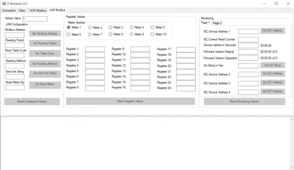
ZTerminal software can be used to read all parameters of LKM devices, alter parameters that are allowed to change and read all registers for all meters connected to LKM devices. This is unoffical software for LKM series of devices and it is an implementation of Modbus commands only.
It supports both Modbus RTU and Modbus TCP ( LKMs connected behind CKL series Modbus TCP to RTU gateway for example) communication.

WARNING: Firmware upgrade is available from Modem side Serial Line only
RS232 on LKM111 & LKM141
RS485 on LKM114 & LKM124 & LKM144 & LKM614
Device and abcZ must be on same serial settings. Lets say if LKM is in Mode 4: 9600 8N1 mode, then abcZ should also be set same for firmware upgrade process.
LKM Series Electricity Meter Protocol to Modbus RTU Protocol Gateways has capability to change firmware from serial line of Modem side. This way the user can get latest updates or change OBIS codes for device operation and also user may also ask for changes. Here are some examples:
Firmware upgrade for specific meter model and protocol implementation
Firmware upgrade to disable switches and work only in one mode
Firmware upgrade to put any feature that user needs
Firmware upgrade procedure need specific firmware file prepared by our company and the firmware upgrade software abcZ software also developed by our company.
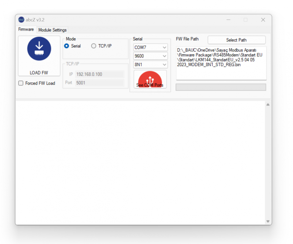
In order to use the software the specific firmware must be selected. After selecting the firmware path by clicking "Select Path" button the firmware can be loaded to device.

NOTE: The device has protection time window 10 seconds after the powered up so the process must be started within 10 seconds after the device powered up.
User can select the correct COM port and click "LOAD FW" button. Both the software and the device will show the percentage of process visually by process bar in software and by LEDs (work mode LEDs) on device (once %25 of process finished LED1 will be on and continue with LED2, LED3 and finish with LED4 after %100 finished). The process will take less than a minute and the device will be ready to use with new firmware after an automatic restart.
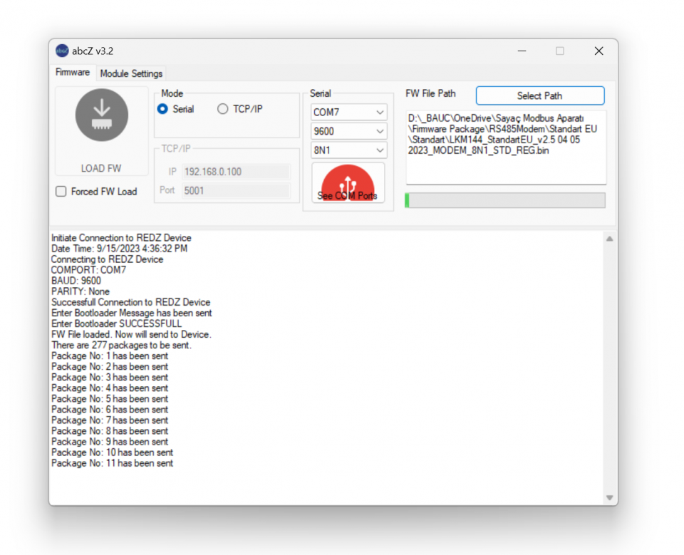

NOTE: If somehow the firmware upgrade process is interrupted and upload file has failed, the device will lose firmware and stay in bootloader mode. In that case user can try upgrading the firmware again and this time should mark the "Forced FW Load" check box.
In this example we are using:
| OBIS_EURO |
"0.9.1", "0.9.2", "1.8.0", "2.8.0", "3.8.0", "4.8.0", "5.8.0", "6.8.0", "7.8.0", "8.8.0", "1.6.0", "2.6.0",
"1.5.0", "1.7.0", "31.7.0", "51.7.0", "71.7.0", "32.7.0", "52.7.0", "72.7.0", "13.7.0", "14.7.0", "C.1.0", "16.7.0" |
|
F.F(11111111) 0.9.2(22-09-14) 0.9.1(10:25:07) 0.1.0(55) 0.1.0*07(22-07-09 02:40) 0.1.0*06(22-07-01 00:00) 0.1.0*05(22-06-01 00:00) 0.1.0*04(22-05-01 00:00) 0.0.0(96130289) C.90.1(96130289) C.1.0(96130289) 1.4.0(02)(3.3132*kW) 2.4.0(02)(4.4444*kW) 5.4.0(04)(5.5148*kvar) 6.4.0(04)(6.6666*kvar) 7.4.0(04)(7.7777*kvar) 8.4.0(04)(8.8888*kvar) 1.5.0(1.1923*kW) 2.5.0(2.2222*kW) 5.5.0(3.3522*kvar) 6.5.0(4.4444*kvar) 7.5.0(5.5555*kvar) 8.5.0(6.6666*kvar) 1.6.0(1.1781*kW)(22-07-11 16:00) 1.6.0*07(0.6450*kW)(22-07-02 23:00) 1.6.0*06(0.3220*kW)(22-06-08 12:15) 1.6.0*05(0.3530*kW)(22-05-25 12:30) 1.6.0*04(0.4110*kW)(22-04-11 11:00) 2.6.0(0.0000*kW)(22-07-12 06:45) 2.6.0*07(0.0360*kW)(22-07-04 04:30) 2.6.0*06(0.0200*kW)(22-06-27 06:30) 2.6.0*05(0.0000*kW)(00-00-00 00:00) 2.6.0*04(0.0000*kW)(00-00-00 00:00) 5.6.0(3.3642*kvar)(22-09-01 10:00) 6.6.0(4.4133*kvar)(22-09-05 07:30) 7.6.0(5.5555*kvar)(22-09-05 07:00) 8.6.0(6.6666*kvar)(22-09-01 09:45) 1.8.1(1151.9956*kWh) 1.8.1*07(1150.9763*kWh) 1.8.1*06(1147.6604*kWh) 1.8.1*05(1126.5102*kWh) 1.8.1*04(1100.1469*kWh) |
1.8.2(7871.4117*kWh) 1.8.2*07(0871.0696*kWh) 1.8.2*06(0868.9837*kWh) 1.8.2*05(0858.9924*kWh) 1.8.2*04(0845.4907*kWh) 1.8.3(4871.8240*kWh) 1.8.3*07(4866.5860*kWh) 1.8.3*06(4853.1543*kWh) 1.8.3*05(4769.7803*kWh) 1.8.3*04(4661.9428*kWh) 2.8.1(7777.6678*kWh) 2.8.1*07(0000.6676*kWh) 2.8.1*06(0000.6665*kWh) 2.8.1*05(0000.6654*kWh) 2.8.1*04(0000.6654*kWh) 2.8.2(8888.1034*kWh) 2.8.2*07(0000.1034*kWh) 2.8.2*06(0000.1034*kWh) 2.8.2*05(0000.1032*kWh) 2.8.2*04(0000.1032*kWh) 2.8.3(9992.9146*kWh) 2.8.3*07(0002.9047*kWh) 2.8.3*06(0002.8053*kWh) 2.8.3*05(0002.7529*kWh) 2.8.3*04(0002.7529*kWh) 5.8.1(1370.6718*kvarh) 5.8.1*07(0370.2462*kvarh) 5.8.1*06(0369.0621*kvarh) 5.8.1*05(0362.3924*kvarh) 5.8.1*04(0355.0516*kvarh) 5.8.2(2269.7377*kvarh) 5.8.2*07(0269.6222*kvarh) 5.8.2*06(0268.9545*kvarh) 5.8.2*05(0265.9975*kvarh) 5.8.2*04(0262.3601*kvarh) 5.8.3(1489.6986*kvarh) 5.8.3*07(1487.8907*kvarh) 5.8.3*06(1483.1537*kvarh) 5.8.3*05(1459.0583*kvarh) 5.8.3*04(1430.8188*kvarh) 6.8.1(3333.7030*kvarh) 6.8.1*07(0000.7002*kvarh) 6.8.1*06(0000.6966*kvarh) 6.8.1*05(0000.6918*kvarh) 6.8.1*04(0000.6918*kvarh) 6.8.2(4444.1706*kvarh) 6.8.2*07(0000.1706*kvarh) 6.8.2*06(0000.1704*kvarh) 6.8.2*05(0000.1673*kvarh) 6.8.2*04(0000.1673*kvarh) |
6.8.3(5553.8802*kvarh) 6.8.3*07(0003.8495*kvarh) 6.8.3*06(0003.6191*kvarh) 6.8.3*05(0003.4521*kvarh) 6.8.3*04(0003.4521*kvarh) 7.8.1(6666.6666*kvarh) 7.8.1*07(0000.0000*kvarh) 7.8.1*06(0000.0000*kvarh) 7.8.1*05(0000.0000*kvarh) 7.8.1*04(0000.0000*kvarh) 7.8.2(7777.7772*kvarh) 7.8.2*07(0000.0002*kvarh) 7.8.2*06(0000.0002*kvarh) 7.8.2*05(0000.0002*kvarh) 7.8.2*04(0000.0002*kvarh) 7.8.3(8888.8881*kvarh) 7.8.3*07(0000.0001*kvarh) 7.8.3*06(0000.0001*kvarh) 7.8.3*05(0000.0001*kvarh) 7.8.3*04(0000.0001*kvarh) 8.8.1(9999.9912*kvarh) 8.8.1*07(0000.0012*kvarh) 8.8.1*06(0000.0012*kvarh) 8.8.1*05(0000.0012*kvarh) 8.8.1*04(0000.0012*kvarh) 8.8.2(1111.1127*kvarh) 8.8.2*07(0000.0027*kvarh) 8.8.2*06(0000.0003*kvarh) 8.8.2*05(0000.0003*kvarh) 8.8.2*04(0000.0003*kvarh) 8.8.3(2222.0685*kvarh) 8.8.3*07(0000.0679*kvarh) 8.8.3*06(0000.0677*kvarh) 8.8.3*05(0000.0676*kvarh) 8.8.3*04(0000.0676*kvarh) 1.8.5(3333.3333*kWh) 1.8.5*07(0000.0000*kWh) 1.8.5*06(0000.0000*kWh) 1.8.5*05(0000.0000*kWh) 1.8.5*04(0000.0000*kWh) 1.8.0(6895.2317*kWh) 1.8.0*07(6888.6320*kWh) 1.8.0*06(6869.7985*kWh) 1.8.0*05(6755.2830*kWh) 1.8.0*04(6607.5805*kWh) 2.8.0(4443.6859*kWh) 3.8.0(4443.6859*kWh) 4.8.0(4443.6859*kWh) 2.8.0*07(0003.6759*kWh) |
2.8.0*06(0003.5753*kWh) 2.8.0*05(0003.5216*kWh) 2.8.0*04(0003.5216*kWh) 5.8.0(2130.1081*kvarh) 5.8.0*07(2127.7592*kvarh) 5.8.0*06(2121.1704*kvarh) 5.8.0*05(2087.4483*kvarh) 5.8.0*04(2048.2306*kvarh) 6.8.0(5554.7538*kvarh) 6.8.0*07(0004.7205*kvarh) 6.8.0*06(0004.4862*kvarh) 6.8.0*05(0004.3113*kvarh) 6.8.0*04(0004.3113*kvarh) 7.8.0(6666.6663*kvarh) 7.8.0*07(0000.0003*kvarh) 7.8.0*06(0000.0003*kvarh) 7.8.0*05(0000.0003*kvarh) 7.8.0*04(0000.0003*kvarh) 8.8.0(7777.7725*kvarh) 8.8.0*07(0000.0719*kvarh) 8.8.0*06(0000.0693*kvarh) 8.8.0*05(0000.0691*kvarh) 8.8.0*04(0000.0691*kvarh) 9.8.0(7788.3984*kVAh) 32.7.0(160.2*V) 52.7.0(160.7*V) 72.7.0(160.6*V) 1.7.0(10.72*A) 31.7.0(10.72*A) 51.7.0(10.72*A) 71.7.0(10.68*A) 91.7.0(10.07*A) 14.7(50.01*Hz) 81.7.0( 110*Deg) 81.7.1( 121*Deg) 81.7.2( 240*Deg) 81.7.4( 116*Deg) 81.7.5( 140*Deg) 81.7.6( 257*Deg) 16.7.0(-10000.114*kW) 131.7.0(22222.222*kvar) 13.7.0(-1.000) 14.7.0(-1.000) 0.2.2(B 23) 0.4.2(00000001) 0.4.3(00000001) |
Open Zterminal software and enter communication parameters. In this example COM port is COM7, baud is set to 19200 and Device selected as "Modbus RTU"
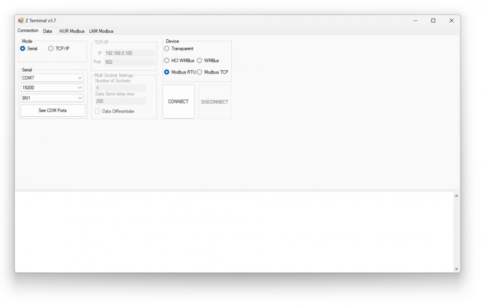
Go to LKM Modbus page and enter Modbus Address of LKM ( default is 1) and click "Read Configured Values".
Page will show device configuration parameters. User can change

NOTE: LKM141, LKM144 supports reading up to 10 meters on RS485 bus and reads 24 registers from each.
LKM111, LKM114 has RS232 interface on meter side, so they support reading 1 meter
LKM124 has P1 Companion Standard interface on meter side, so it supports reading 1 meter
LKM614 directly fits in EMH LZQJ-XC series meters, so it supports reading 1 meter

NOTE: LKM series has version to read 64 registers from up to 4 meters ( LKM141 and LKM144 models can read more than 1 meters) as well. Users may order (or change firmware later in the field) based on their need.
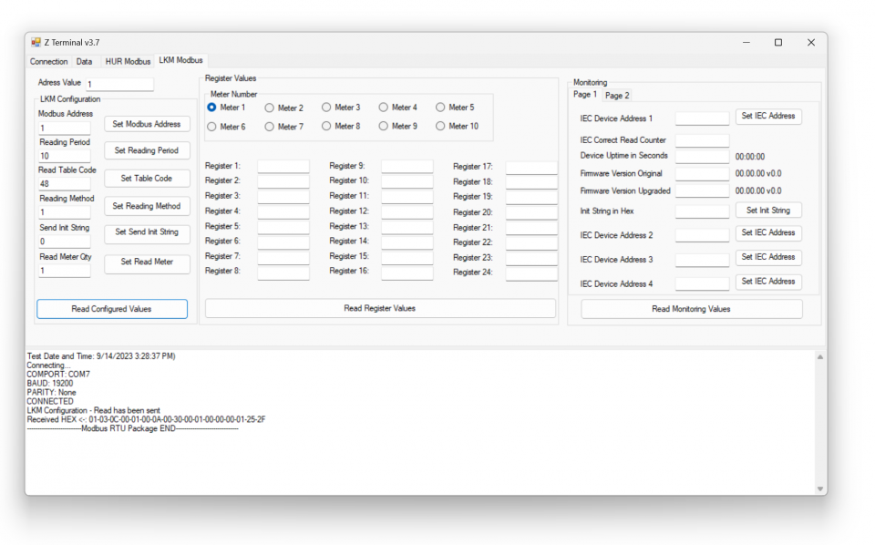
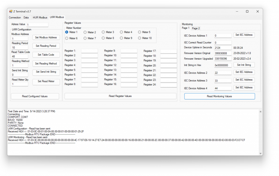
Click "Monitoring".
Page will show device monitoring parameters. User can also change read meter device address from this part.

NOTE: If there are more than 1 meters on RS485 bus, user MUST enter the physical addresses of meters to read teh correct meter.

NOTE: LKM restarts itself in every 24 hours automatically.
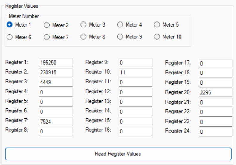
Click "Meter 1" to read values of 1st Meter.
System will show the read values ( without notation)
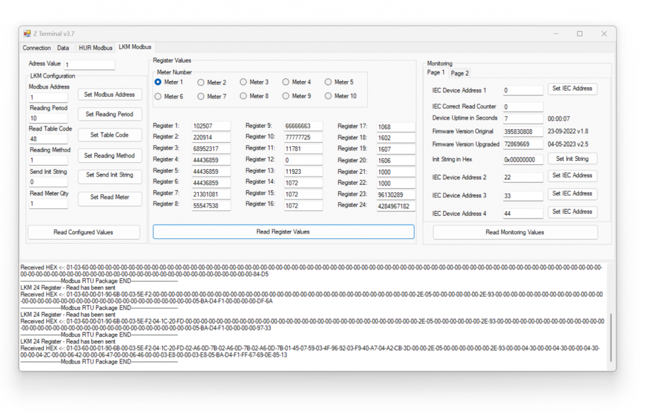
Here is mapping based on our example and it perfectly matches with ZTerminal screen
| Register Number | Obis Code | Found in |
|
1 |
"0.9.1" |
0.9.1(10:25:07) |
|
2 |
"0.9.2" |
0.9.2(22-09-14) |
|
3 |
"1.8.0" |
1.8.0(6895.2317*kWh) |
|
4 |
"2.8.0" |
2.8.0(4443.6859*kWh) |
|
5 |
"3.8.0" |
3.8.0(4443.6859*kWh) |
|
6 |
"4.8.0" |
4.8.0(4443.6859*kWh) |
|
7 |
"5.8.0" |
5.8.0(2130.1081*kvarh) |
|
8 |
"6.8.0" |
6.8.0(5554.7538*kvarh) |
|
9 |
"7.8.0" |
7.8.0(6666.6663*kvarh) |
|
10 |
"8.8.0" |
8.8.0(7777.7725*kvarh) |
|
11 |
"1.6.0" |
1.6.0(1.1781*kW)(22-07-11 16:00) |
|
12 |
"2.6.0" |
2.6.0(0.0000*kW)(22-07-12 06:45) |
|
13 |
"1.5.0" |
1.5.0(1.1923*kW) |
|
14 |
"1.7.0" |
1.7.0(10.72*A) |
|
15 |
"31.7.0" |
31.7.0(10.72*A) |
|
16 |
"51.7.0" |
51.7.0(10.72*A) |
|
17 |
"71.7.0" |
71.7.0(10.68*A) |
|
18 |
"32.7.0" |
32.7.0(160.2*V) |
|
19 |
"52.7.0" |
52.7.0(160.7*V) |
|
20 |
"72.7.0" |
72.7.0(160.6*V) |
|
21 |
"13.7.0" |
13.7.0(-1.000) |
|
22 |
"14.7.0" |
14.7.0(-1.000) |
|
23 |
"C.1.0" |
C.1.0(96130289) |
|
24 |
"16.7.0" |
16.7.0(-10000.114*kW) |

NOTE: This reading is done with a simulator software created by our company. Thus some values are artificial. Also Zterminal do not parse negative values ( user modbus software can easly do it by changing data type)
LKM141, LKM144 supports reading up to 10 meters on RS485 bus and reads 24 registers from each meters. They have also version for 64 registers of 4 meters.
If there are more than 1 meter on RS485 bus, user MUST enter the physicall addresses of meters to read the correct meter.
In "LKM Configuration" part set the number of meters needed to be read and click "Set Read Meter". In this example we have 2 meters on RS485 bus.
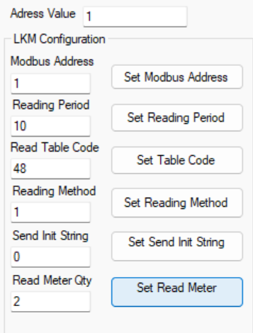
In "Monitoring" part set the physical address for meter 1 and click "Set IEC Address". In this example we will set 67269821.
Again in same window set the physicall address for meter 1 and click "Set IEC Address". In this example we will set 12699119.
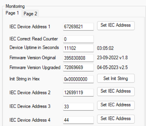
Then LKM will read meters 1 by 1
In "Monitoring" part select "Meter 1" and click "Read Register Values", ZTerminal will show read values for Meter 1
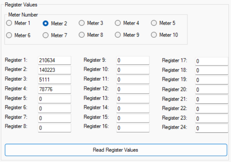
In same way in "Monitoring" part select "Meter 2" and click "Read Register Values", ZTerminal will show read values for Meter 2
In this example we are using:
| OBIS_EURO |
"0.9.1", "0.9.2", "1.8.0", "2.8.0", "3.8.0", "4.8.0", "5.8.0", "6.8.0", "7.8.0", "8.8.0", "1.6.0", "2.6.0",
"1.5.0", "1.7.0", "31.7.0", "51.7.0", "71.7.0", "32.7.0", "52.7.0", "72.7.0", "13.7.0", "14.7.0", "C.1.0", "16.7.0" |
|
F.F(11111111) 0.9.2(22-09-14) 0.9.1(10:25:07) 0.1.0(55) 0.1.0*07(22-07-09 02:40) 0.1.0*06(22-07-01 00:00) 0.1.0*05(22-06-01 00:00) 0.1.0*04(22-05-01 00:00) 0.0.0(96130289) C.90.1(96130289) C.1.0(96130289) 1.4.0(02)(3.3132*kW) 2.4.0(02)(4.4444*kW) 5.4.0(04)(5.5148*kvar) 6.4.0(04)(6.6666*kvar) 7.4.0(04)(7.7777*kvar) 8.4.0(04)(8.8888*kvar) 1.5.0(1.1923*kW) 2.5.0(2.2222*kW) 5.5.0(3.3522*kvar) 6.5.0(4.4444*kvar) 7.5.0(5.5555*kvar) 8.5.0(6.6666*kvar) 1.6.0(1.1781*kW)(22-07-11 16:00) 1.6.0*07(0.6450*kW)(22-07-02 23:00) 1.6.0*06(0.3220*kW)(22-06-08 12:15) 1.6.0*05(0.3530*kW)(22-05-25 12:30) 1.6.0*04(0.4110*kW)(22-04-11 11:00) 2.6.0(0.0000*kW)(22-07-12 06:45) 2.6.0*07(0.0360*kW)(22-07-04 04:30) 2.6.0*06(0.0200*kW)(22-06-27 06:30) 2.6.0*05(0.0000*kW)(00-00-00 00:00) 2.6.0*04(0.0000*kW)(00-00-00 00:00) 5.6.0(3.3642*kvar)(22-09-01 10:00) 6.6.0(4.4133*kvar)(22-09-05 07:30) 7.6.0(5.5555*kvar)(22-09-05 07:00) 8.6.0(6.6666*kvar)(22-09-01 09:45) 1.8.1(1151.9956*kWh) 1.8.1*07(1150.9763*kWh) 1.8.1*06(1147.6604*kWh) 1.8.1*05(1126.5102*kWh) 1.8.1*04(1100.1469*kWh) 1.8.2(7871.4117*kWh) 1.8.2*07(0871.0696*kWh) 1.8.2*06(0868.9837*kWh) 1.8.2*05(0858.9924*kWh) 1.8.2*04(0845.4907*kWh) |
1.8.3(4871.8240*kWh) 1.8.3*07(4866.5860*kWh) 1.8.3*06(4853.1543*kWh) 1.8.3*05(4769.7803*kWh) 1.8.3*04(4661.9428*kWh) 2.8.1(7777.6678*kWh) 2.8.1*07(0000.6676*kWh) 2.8.1*06(0000.6665*kWh) 2.8.1*05(0000.6654*kWh) 2.8.1*04(0000.6654*kWh) 2.8.2(8888.1034*kWh) 2.8.2*07(0000.1034*kWh) 2.8.2*06(0000.1034*kWh) 2.8.2*05(0000.1032*kWh) 2.8.2*04(0000.1032*kWh) 2.8.3(9992.9146*kWh) 2.8.3*07(0002.9047*kWh) 2.8.3*06(0002.8053*kWh) 2.8.3*05(0002.7529*kWh) 2.8.3*04(0002.7529*kWh) 5.8.1(1370.6718*kvarh) 5.8.1*07(0370.2462*kvarh) 5.8.1*06(0369.0621*kvarh) 5.8.1*05(0362.3924*kvarh) 5.8.1*04(0355.0516*kvarh) 5.8.2(2269.7377*kvarh) 5.8.2*07(0269.6222*kvarh) 5.8.2*06(0268.9545*kvarh) 5.8.2*05(0265.9975*kvarh) 5.8.2*04(0262.3601*kvarh) 5.8.3(1489.6986*kvarh) 5.8.3*07(1487.8907*kvarh) 5.8.3*06(1483.1537*kvarh) 5.8.3*05(1459.0583*kvarh) 5.8.3*04(1430.8188*kvarh) 6.8.1(3333.7030*kvarh) 6.8.1*07(0000.7002*kvarh) 6.8.1*06(0000.6966*kvarh) 6.8.1*05(0000.6918*kvarh) 6.8.1*04(0000.6918*kvarh) 6.8.2(4444.1706*kvarh) 6.8.2*07(0000.1706*kvarh) 6.8.2*06(0000.1704*kvarh) 6.8.2*05(0000.1673*kvarh) 6.8.2*04(0000.1673*kvarh) |
6.8.3(5553.8802*kvarh) 6.8.3*07(0003.8495*kvarh) 6.8.3*06(0003.6191*kvarh) 6.8.3*05(0003.4521*kvarh) 6.8.3*04(0003.4521*kvarh) 7.8.1(6666.6666*kvarh) 7.8.1*07(0000.0000*kvarh) 7.8.1*06(0000.0000*kvarh) 7.8.1*05(0000.0000*kvarh) 7.8.1*04(0000.0000*kvarh) 7.8.2(7777.7772*kvarh) 7.8.2*07(0000.0002*kvarh) 7.8.2*06(0000.0002*kvarh) 7.8.2*05(0000.0002*kvarh) 7.8.2*04(0000.0002*kvarh) 7.8.3(8888.8881*kvarh) 7.8.3*07(0000.0001*kvarh) 7.8.3*06(0000.0001*kvarh) 7.8.3*05(0000.0001*kvarh) 7.8.3*04(0000.0001*kvarh) 8.8.1(9999.9912*kvarh) 8.8.1*07(0000.0012*kvarh) 8.8.1*06(0000.0012*kvarh) 8.8.1*05(0000.0012*kvarh) 8.8.1*04(0000.0012*kvarh) 8.8.2(1111.1127*kvarh) 8.8.2*07(0000.0027*kvarh) 8.8.2*06(0000.0003*kvarh) 8.8.2*05(0000.0003*kvarh) 8.8.2*04(0000.0003*kvarh) 8.8.3(2222.0685*kvarh) 8.8.3*07(0000.0679*kvarh) 8.8.3*06(0000.0677*kvarh) 8.8.3*05(0000.0676*kvarh) 8.8.3*04(0000.0676*kvarh) 1.8.5(3333.3333*kWh) 1.8.5*07(0000.0000*kWh) 1.8.5*06(0000.0000*kWh) 1.8.5*05(0000.0000*kWh) 1.8.5*04(0000.0000*kWh) 1.8.0(6895.2317*kWh) 1.8.0*07(6888.6320*kWh) 1.8.0*06(6869.7985*kWh) 1.8.0*05(6755.2830*kWh) 1.8.0*04(6607.5805*kWh) 2.8.0(4443.6859*kWh) 3.8.0(4443.6859*kWh) 4.8.0(4443.6859*kWh) 2.8.0*07(0003.6759*kWh) |
2.8.0*06(0003.5753*kWh) 2.8.0*05(0003.5216*kWh) 2.8.0*04(0003.5216*kWh) 5.8.0(2130.1081*kvarh) 5.8.0*07(2127.7592*kvarh) 5.8.0*06(2121.1704*kvarh) 5.8.0*05(2087.4483*kvarh) 5.8.0*04(2048.2306*kvarh) 6.8.0(5554.7538*kvarh) 6.8.0*07(0004.7205*kvarh) 6.8.0*06(0004.4862*kvarh) 6.8.0*05(0004.3113*kvarh) 6.8.0*04(0004.3113*kvarh) 7.8.0(6666.6663*kvarh) 7.8.0*07(0000.0003*kvarh) 7.8.0*06(0000.0003*kvarh) 7.8.0*05(0000.0003*kvarh) 7.8.0*04(0000.0003*kvarh) 8.8.0(7777.7725*kvarh) 8.8.0*07(0000.0719*kvarh) 8.8.0*06(0000.0693*kvarh) 8.8.0*05(0000.0691*kvarh) 8.8.0*04(0000.0691*kvarh) 9.8.0(7788.3984*kVAh) 32.7.0(160.2*V) 52.7.0(160.7*V) 72.7.0(160.6*V) 1.7.0(10.72*A) 31.7.0(10.72*A) 51.7.0(10.72*A) 71.7.0(10.68*A) 91.7.0(10.07*A) 14.7(50.01*Hz) 81.7.0( 110*Deg) 81.7.1( 121*Deg) 81.7.2( 240*Deg) 81.7.4( 116*Deg) 81.7.5( 140*Deg) 81.7.6( 257*Deg) 16.7.0(-10000.114*kW) 131.7.0(22222.222*kvar) 13.7.0(-1.000) 14.7.0(-1.000) 0.2.2(B 23) 0.4.2(00000001) 0.4.3(00000001) |
Open Modbus Poll Software and enter communication parameters under menu "Connection"-> "Connect".
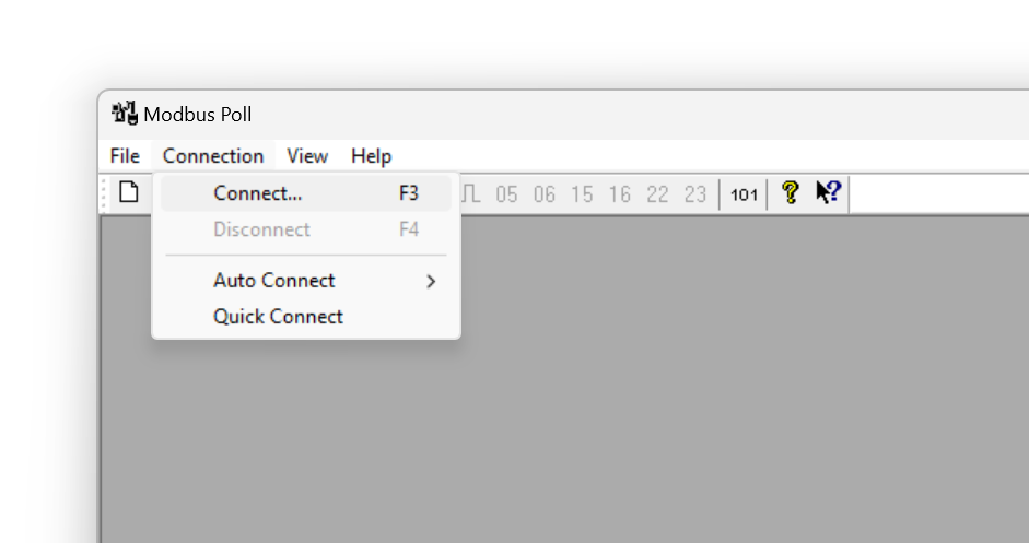
In this example COM port is COM7, baud is set to 19200 and data is 8 Data Bits, 1 Stop Bit and Parity is None.
Device will be connected over Serial Port ( Modbus RTU). Click "OK" to save settings.
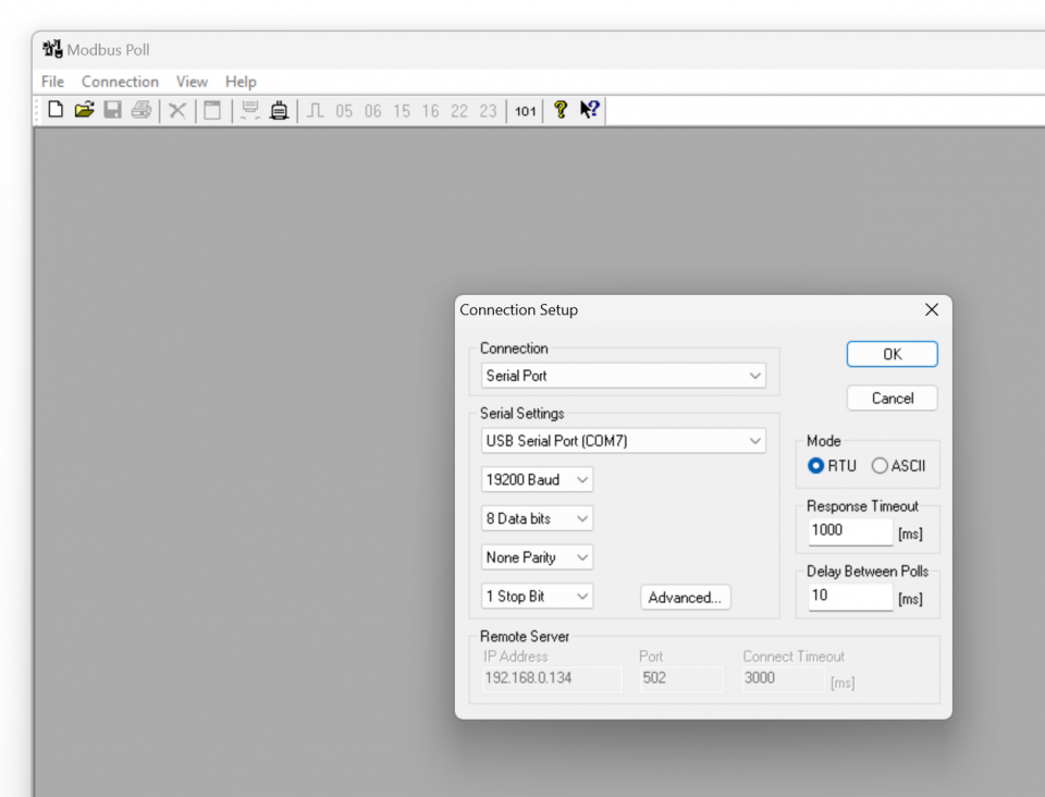
Click "File"->"New" to open a new reading window. Right click from mouse to newly opened window to select "Read/write Defitinion..."
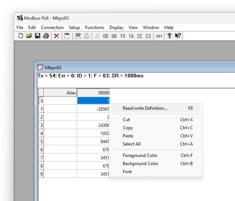
Modbus Address will be in this example. Function will be "03 Read Holding Register (4x).
Register start address will be 0 in this example

NOTE: Register address for different number of meters ( for LKM141 and LKM144 models) are will be as follows
Meter 1: Hex: 0x00 00, Decimal 0
Meter 2: Hex: 0x01 00, Decimal 256
Meter 3: Hex: 0x02 00, Decimal 512
...
Meter 10: Hex: 0x09 00, Decimal 2304
If there are more than 1 meters on RS485 bus, user MUST enter the physical addresses of meters to read the correct meter. It can be entered by using Modbus commands described in this manual or by using ZTerminal Software as described in previous part.
to read 24 long type registers we must query 48 values

NOTE: If the device in 64 registers reading firmware , then to read 64 long type registers we must query 128 values. The software may not allow that big number, so user can open 2 windows and split quey in half
1st window: Query Register 0 - Qty 64
2nd window: Query Register 65 - Qty 64
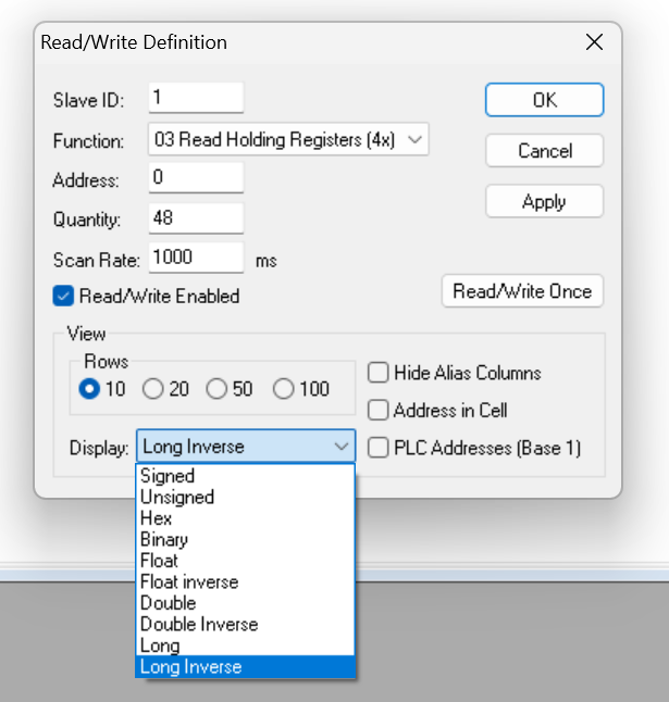
Click "OK" when finished and software will read values
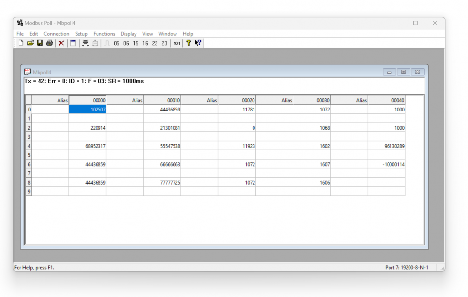
Here is mapping based on our example and it perfectly matches with Modbus reading screen
| Register Number | Obis Code | Found in |
|
1 |
"0.9.1" |
0.9.1(10:25:07) |
|
2 |
"0.9.2" |
0.9.2(22-09-14) |
|
3 |
"1.8.0" |
1.8.0(6895.2317*kWh) |
|
4 |
"2.8.0" |
2.8.0(4443.6859*kWh) |
|
5 |
"3.8.0" |
3.8.0(4443.6859*kWh) |
|
6 |
"4.8.0" |
4.8.0(4443.6859*kWh) |
|
7 |
"5.8.0" |
5.8.0(2130.1081*kvarh) |
|
8 |
"6.8.0" |
6.8.0(5554.7538*kvarh) |
|
9 |
"7.8.0" |
7.8.0(6666.6663*kvarh) |
|
10 |
"8.8.0" |
8.8.0(7777.7725*kvarh) |
|
11 |
"1.6.0" |
1.6.0(1.1781*kW)(22-07-11 16:00) |
|
12 |
"2.6.0" |
2.6.0(0.0000*kW)(22-07-12 06:45) |
|
13 |
"1.5.0" |
1.5.0(1.1923*kW) |
|
14 |
"1.7.0" |
1.7.0(10.72*A) |
|
15 |
"31.7.0" |
31.7.0(10.72*A) |
|
16 |
"51.7.0" |
51.7.0(10.72*A) |
|
17 |
"71.7.0" |
71.7.0(10.68*A) |
|
18 |
"32.7.0" |
32.7.0(160.2*V) |
|
19 |
"52.7.0" |
52.7.0(160.7*V) |
|
20 |
"72.7.0" |
72.7.0(160.6*V) |
|
21 |
"13.7.0" |
13.7.0(-1.000) |
|
22 |
"14.7.0" |
14.7.0(-1.000) |
|
23 |
"C.1.0" |
C.1.0(96130289) |
|
24 |
"16.7.0" |
16.7.0(-10000.114*kW) |

NOTE: This reading is done with a simulator software created by our company. Thus some values are artificial.
LKM614 Electricity Meter Protocol to Modbus RTU Protocol Gateway is especially designed for EMH LZQJ-XC meters and it is direct replacement for Variomod XC modules. LKM614 can be connected to EMH LZQJ-SC meter in fixed baud rate or auto baud rate mode based on meter settings. Other side of device can be connected to a field device such as PLC or RTU and that device can read data with Modbus RTU protocol. That device can also be connected to REDZ CKL series Modbus TCP – RTU Converter to read Modbus values over LAN or WAN.

Here is an example for montage and meter data reading via Modbus software ZTerminal
Here is an example video reading over Modbus software ZTerminal
LKM Series Electricity Meter Protocol to Modbus RTU Protocol Gateways can be connected to optical probe of meter via REDZ KMK series optical probes and can operate in changing baud rate mode. Other side of device can be connected to remote Data Acquisition Server via Modbus RTU or via TCP/IP device that can convert Modbus TCP to Modbus RTU.

Here is an example for meter data reading over KMK114 - RS485 Optical Probe and LKM144 via Modbus software ZTerminal. USB to RS485 converter used to read LKM in this video.
Here is an example for meter data reading over KMK114 - RS485 Optical Probe and LKM144 via Modbus software ZTerminal and this time LKM is connected to CKL series to read data over TCP/IP.
LKM Series Electricity Meter Protocol to Modbus RTU Protocol Gateways can be connected to RS485 or P1 serial line of meter and can operate in fixed baud rate mode. Other side of device can be connected to a field device such as PLC or RTU and that device can read data with Modbus RTU protocol.

Here is connnection pin fiagram for connecting P1 interface
Meter Side: LKM124

| Pin Number | Description |
| 1 |
Input Power + (5V - 24V DC) |
| 2 |
Input Power - GND |
| 3 | GND |
| 4 | Rx (Data) |
| 5 | CTRL (Data Request) |
User should arrange RJ12 cable needed to connect to meter in desired length.

| Pin Number | Description |
| 1 |
+5V Power Supply |
| 2 |
Data Request (CTRL) |
| 3 | Data GND |
| 4 | Not connected (NC) |
| 5 | Data (Rx) |
| 6 | Power GND |

NOTE: Power Input has polarity protection. Yet again please check polarity when connecting multiple devices in same power source, otherwise device may burn due to worng connection of power.
Here is an example for P1 meter data reading via ZTerminal Windows software.
Here is an example for physicall application.
LKM111: Electricity Meter Protocol to Modbus RTU Protocol Gateway, Modem Side RS232 and Meter Side RS232, 5-24V DC Power Input
LKM114: Electricity Meter Protocol to Modbus RTU Protocol Gateway, Modem Side RS485 and Meter Side RS232, 5-24V DC Power Input
LKM124: Electricity Meter Protocol to Modbus RTU Protocol Gateway, Modem Side RS485 and Meter Side P1 Interface, 5-24V DC Power Input
LKM141: Electricity Meter Protocol to Modbus RTU Protocol Gateway, Modem Side RS232 and Meter Side RS485, 5-24V DC Power Input
LKM144: Electricity Meter Protocol to Modbus RTU Protocol Gateway, Modem Side RS485 and Meter Side RS485, 5-24V DC Power Input
LKM614: Electricity Meter Protocol to Modbus RTU Protocol Gateway, Modem Side RS485 and Meter Side is Direct Connection to Meter, Powered from Meter Interface
| Model | 5-24V DC Power input | Plug into Meter and Play, No external Power Needed |
Operating Mode Selections | Modem Side RS232 Connection | Modem Side RS485 Connection | Meter Side RS232 Connection |
Meter Side RS485 Connection |
Meter Side P1 Companion Standard |
IEC62056-21 Protocol | P1 Companion Standard | Firmware Upgrade Over Serial Line |
| LKM111 | X |
X |
X |
X | X | X |
|||||
| LKM114 | X |
X |
X | X | X | X |
|||||
| LKM124 | X |
X |
X | X | X | X |
|||||
| LKM141 | X | X | X | X | X | X | |||||
| LKM144 | X | X | X | X |
X | X | |||||
| LKM614 | X |
X | X | X |
THIS SITE USES COOKIES
Various types of cookies are used on our website (and on all other digital platforms including mobile applications).
View our new THE INFORMATIVE TEXT ON LPPD AND PRIVACY here.
Google Analytics
Analytical cookies help us to improve our website by collecting and reporting information on its usage.
Google AdWords and Remarketing
We use marketing cookies to help us improve the relevancy of advertising campaigns you receive.
I have read the above articles