- 2.4GHz LoRa based Radio Frequency (RF) Communication
- LoRa Signal Bandwidth Configurable: 200, 400, 800, 1600 kHz
- LoRa Radio Power Configurable between -18dBm (~0,02mW) to 13dBm (~20mW)
- LoRa or FLRC Selectable Modulation Options
- Supports 2 x 10/100Base-T(X) ports
- Supports 1 x RS232 and 1 x RS485 Serial Connection up to 460800 Baud
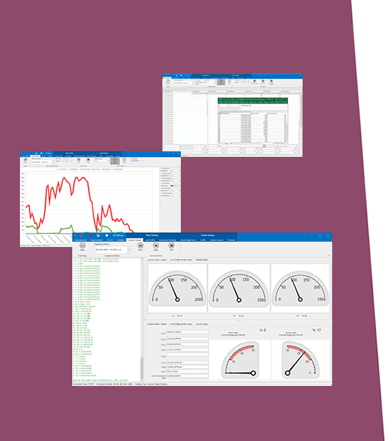
- Embedded web interface for ease of use
- 1 Device with 5 different Gateway Operating Modes:
Transparent Gateway Between TCP Client Devices and LoRa RF Network
Transparent Gateway Between TCP Server Devices and LoRa RF Network
Transparent Gateway Between RS232/RS485 Serial Devices and LoRa RF Network
Modbus TCP to RTU Conversion Gateway for RS232/RS485 Serial Devices for messages over LoRa RF Network
LoRa Repeater
- Creates Radio Network:
Point to point
Point to multi point - Broadcast
Point to multi point - TCP Socket to target address mapping based data transfer
- Auto Discovers the TLM devices in LoRa Network that can be communicated and lists signal levels, addresses and configuration/connection details
- 128 bit AES Encryption and Decryption on over the air communication
- LoRa Rx Group Address and Device Address Configurable
- LoRa Tx Group Address and Device Address Configurable
- Up to 10 client connection in Server Mode
- DHCP Server Capability
- Easy to follow LoRa data packages on web interface
- Easy to follow Device Status on web interface
- Black List and White List based LoRa package filter
- Firmware Upgrade over Web
- 2 firmware storage capability on same device (1 active only)
- Supports 2 x 10/100Base-T(X) ports + 1 x BPL link
- Wide Range 3 phase input, 110V–240V/50-60Hz wide range power input
- Supports up to 30Mbps PHY rate on BPL with Up to 10 hops and 1000 nodes
- Up to 432 sub-carriers from 2 to 28MHz analog bandwidth on BPL
- Support LDPC-C FEC with 128-bit AES core on BPL
- Supports Full/Half-Duplex, auto MDI/MDI-X on each port
- Wide operating temperature range from -40 to 85 °C
- Rugged Metal IP-40 housing design
- DIN-Rail mounting
LoRa TECHNOLOGY - 2.4GHz
Based on
Powerful Cortex M3
Pre-Certified according to EN 300 220
Sensitivity
Down to -130 dBm
Output Power level
Up to 13dBm
Link Budget
Up to 142 dB
Communication Distance
Up to 12km (Line of Sight)
Typical Communication Distance Indoor/Urban
>2km
Frequency Range
Min 2 402 000 137 Hz
Max 2 479 999 939 Hz
LoRa Bandwidth Options
200 kHz, 400 kHz, 800 kHz, 1600 kHz
Tx Power Level
-18dBm (~0,02mW) to 13dBm (~20mW) Configurable
LoRa Spreading Factor
SF5, SF6, SF7, SF8, SF9, SF10, SF11, SF12
Modulation
LoRa or FLRC Selectable
LoRa Network Auto Discovery
TLM automatically discovers all other TLM devices in same LoRa RF Network and lists communication signal levels, addresses and configuration/connection details. This makes setting up LoRa wireless network much easier.
ETHERNET TECHNOLOGY
Ethernet Standards
IEEE 802.3 for 10Base-T
IEEE 802.3u for 100Base-T(X)
IEEE 802.3x Flow Control
Mac Table
1K MAC address entry
Processing
Store-and-Forward
Memory
448K bits packet buffer memory
BPL (BROADBAND POWERLINE) TECHNOLOGY
PHY Data Rate
Up to 240 MHz
MAC Layer Protocol
CSMA/CA
Modulation Technology
OFDM-432
VLAN
IEEE802.1q/ IEEE802.1p/ IEEE802.3d
NTP TIME SYNCHRONIZATION - LoRa Models
NTP is used to synchronize device time after a manual or system triggered restart and it only takes place if NTP time is available and device time difference from NTP time is + or - 24 Hours.
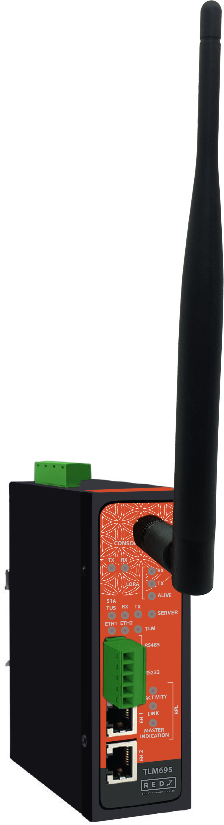
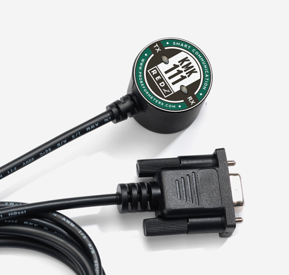
CONNECTORS AND PORTS - LoRa
SMA Antenna Connector for LoRa
1 Standard SMA female interface, 50 ohm
Console Port
USB Type C or Micro USB connection for LOG in 115200 baud
10/100T(X) RJ45 Ports
Ethernet Connection on 2 ports
Serial Ports
5 pin wired Terminal Connection
Tx, Rx, GND for RS232
A, B and GND for RS485
Reset Buttons
Reset to Client and Reset to Server Operating modes buttons
LED INDICATORS
Power Indicator
Power LED
10/100T(X) Indicators
Activity LEDs:
ETH1, ETH2 and Activity of device itself (Marked as device series name, such as CKL/TLM/HUR/LKM)
System Indicators
Status LED,
Tx and Rx of data LEDs and Server LED
Console Indicators
Tx and Rx of data LEDs
LED INDICATORS - BPL
BPL LEDs
-BPL Activity
-BPL Link
-Master Indication (LED ON: Master, LED OFF: Slave)
POWER - BPL
Power Connection
Powering up device is only done over Terminal pins 1 and 2.
Can be purchased in 2 versions:
1. AC Powered version: Device can be powered up with AC input, this option is available in both PN and PP models. It accepts, 110V–240V/50-60Hz. (Power Input can also be used for data transmission in PN Models.)
2. DC Powered version: Device can be powered up with 9-36V DC power. Data transmission only done through terminal pins 3 and 4. This model can be used if DC power source will be used in the field and available with PP or DC model.
Data Connection
Can be purchased in 3 versions:
1. PP Model: Phase to phase model (Standard Model).
Data transmission is only done through terminal pins 3 and 4. AC Phase to phase connection should be done to data transmission pins for better performance. If phase to phase connection is not available then phase and neutral can still be connected for data transmission over terminal pins 3 and 4.
(Ex: L1-L2, L2-L3, L1-L3 or L1-2-3 to N can be used as data connection)
2. PN Model: Phase to neutral model. That version gets power from terminal pins 1 and 2 from phase and neutral and it can also transmit data from that pins (pins 1 and 2). Remaining (pins 3 and 4) pins usage is optional.
(Ex: Master can be connected to all phases and slaves can be connected to relevant phases)
(Ex: L1-N, L2-N, L3-N or L1-2-3 and N can be used as data connection)
3. DC Model: DC data line model. Uses DC Power Line for data transmission. (Ex: 24V+ and GND as data connection)
PHYSICAL AND ENVIRONMENTAL CHARACTERISTICS - DC POWERED AND BPL MODELS
Enclosure
Metal, IP40
Dimensions
43 x 95 x 124 (w x d x h) mm
Weight
~400gr
Storage Temperature
-65 to 150 °C
Operating Temperature
-40 to 85 °C
Operating Humidity
5% to 95% Non-condensing
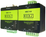
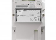
TLM695: 2.4GHz LoRa RF Modem, 2x 10/100 T(x) ETH ports + 1 x BPL (Broadband Power Line) Link, 1 x RS232 & 1 x RS485, 3 Phase AC Power Input, 110V–240V/50-60Hz