- Radio Band Options:
923MHz
AS 923 MHz – BN 923 MHz – Brunei, LoRaWAN RF Communication
AS 923 MHz – KH 923 MHz – Cambodia, LoRaWAN RF Communication
AS 923 MHz – ID 923 MHz – Indonesia, LoRaWAN RF Communication
AS 923 MHz – JP 920 MHz – Japan, LoRaWAN RF Communication
AS 923 MHz – LA 923 MHz – Laos, LoRaWAN RF Communication
AS 923 MHz – NZ 915 MHz – New Zealand, LoRaWAN RF Communication
AS 923 MHz – SG 920 MHz – Singapore, LoRaWAN RF Communication
AS 923 MHz – TW 922 MHz – Taiwan, LoRaWAN RF Communication
AS 923 MHz – TH 920 MHz – Thailand, LoRaWAN RF Communication
AS 923 MHz – VN 920 MHz – Vietnam, LoRaWAN RF Communication
- Built in LoRaWAN Duty Cycle Check for AS923 Models
- Supports 2 x 10/100Base-T(X) ports
- Supports 1 x RS232 and 1 x RS485 Serial Connection up to 460800 Baud
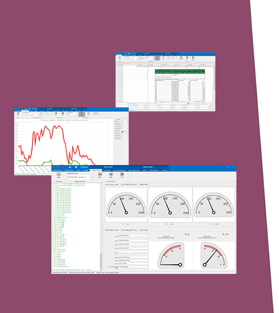
- Embedded web interface for ease of use
- 3 Main Device Functions:
LoRaWAN Modbus TCP Scheduler
LoRaWAN Modbus RTU Scheduler
LoRaWAN Transparent Mode (Transparent bridge between LoRaWAN and TCP/IP or RS232/RS485 Serial Side)
- Up to 64 device connections in Modbus TCP or RTU Scheduler modes
- Up to 10 device connections in Transparent TCP/IP mode
- Modbus Function Code (Function Codes 1-2-3-4 are supported), Register Address, Total Register Number, Query Interval, Time Out durations and Minimum Interval for LoRaWAN Data Send can be defined for each field device seperately.
- Downlink Message supported for remote control of field Modbus TCP or RTU Devices. Modbus Function Codes 1-2-3-4-5-6 are supported as downlink Modbus Command.
- Built in LoRaWAN Payload Size Check Function. User can read any data in any size, TLM will automatically split based on Maximum Payload Size allowed and Duty Cycle Block Times.
- Activation Over Air (OTAA) or Activation by Personalization (ABP) Selectable
- User defined LoRAWAN Port
- Adaptive Data Rate functionality
- Selectable Uplink Data Rate
- Selectable Power Level
- LoRaWAN Class C and Class A support
- Easy monitor of transmitted data on web interface
- Easy to follow Device Status and Modbus data packages on web interface
- Easy to follow LoRaWAN packages on web interface
- DHCP Server Capability
- Black List and White List based IP Filter in TCP Server Mode
- Firmware Upgrade over Web
- 2 firmware storage capability on same device (1 active only)
- 5-48V DC wide range power input (allows up to 60 V DC)
- Wide operating temperature range from -40 to 85 °C
- Rugged Metal IP-40 housing design
- DIN-Rail mounting
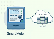
LoRaWAN TECHNOLOGY
Based on
STM32L151CxU6Axx
Pre-Certified according to EN 300 220
Sensitivity
Down to -138 dBm
Link Budget
Up to 156 dB
Communication Distance
Up to 15km (Line of Sight)
Typical Communication Distance Indoor/Urban
>2km
LoRaWAN Activation Options
Activation Over Air (OTAA)
Activation by Personalization (ABP)
User Selectable
LoRaWAN Port
User Selectable
Adaptive Data Rate
Available
LoraWAN Class
Class A
Class C
Time Synchronization
Device synchronizes its time with LoRaWAN Server right after it is connected to LoRaWAN Server
LoRaWAN TECHNOLOGY - 923MHz
Uplink Data Rate
SF10 / 125 kHz / 980 bps
SF9 / 125 kHz / 1760 bps
SF8 / 125 kHz / 3125 bps
SF7 / 125 kHz / 5470 bps
Tx Power Level
0 to 16dBm Configurable
LoRaWAN Downlink Details - TLM
Downlink Messages
Modbus Commands are supported as Downlink Message for Modbus TCP and RTU Scheduler Function.
Downlink Messages are sent to field TCP/IP or RS232/RS485 serial device as it is in Transparent Data Send Function.
Function Codes for Modbus TCP and RTU Scheduler
Read Coil Status (FC=1)
Read Input Status (FC=2)
Read Holding Registers (FC=3)
Read Input Registers (FC=4)
Force Single Coil (FC=5)
Preset Single Register (FC=6)
are supported.
ETHERNET TECHNOLOGY
Ethernet Standards
IEEE 802.3 for 10Base-T
IEEE 802.3u for 100Base-T(X)
IEEE 802.3x Flow Control
Mac Table
1K MAC address entry
Processing
Store-and-Forward
Memory
448K bits packet buffer memory
NTP TIME SYNCHRONIZATION - LoRaWAN Models
NTP is used to synchronize device time after a manual or system triggered restart and it only takes place if NTP time is available and device time difference from NTP time is + or - 24 Hours.
Device synchronize time with LoRaWAN Server as well after first succesfull connection and it has higher priority than NTP time synchronization.
LoRaWAN UPLINK DETAILS - TLM
Status Message - Device Status
Message sent to LoRaWAN Port number 1, in every connection to LoRaWAN Server
4 Bytes: TLM unique Device Id
1 Byte: Frame Type (Lower 4 bits) and Package Number (Upper 4 bits). If Package Number is 1 or more that means the package splitted.
0x00 : means status package for device status and package is the first package
1 Byte: Number of Modbus devices configured to be read
1 Byte: LoRaWAN Port of the response package
4 Bytes: RTC Time
3 Bytes: TLM Device firmware version
N Bytes (maximum 22): TLM Device name configured by user
Modbus Data Message
Message sent to LoRaWAN configured Port (default is 3) and minimum send interval defined in command settings.
4 Bytes: TLM unique Device Id
1 Byte: Frame Type (Lower 4 bits) and Package Number (Upper 4 bits). If Package Number is 1 or more that means the package splitted.
0x01: means Modbus RTU Payload and this is the first package
1 Byte: Modbus Slave Device Address
1 Byte: Modbus Function Code
2 Bytes: Modbus Data Start Address
2 Bytes: Modbus Data Total Registers
1 Byte: Total Data Size in Payload
Modbus Data Frames are shared afterwards based on Total Data Size in Payload
1 or 2 Bytes: Modbus Register Data
....Next data that maximum payload size allows
MODBUS DETAILS - TLM LoRAWAN
Modbus Protocol
Modbus TCP or RTU Selectable by User
Modbus Devices
Up to 64 Modbus commands can be defined by User
Modbus Address
Independently selectable by User
Modbus Function Code
Read Coil Status (FC=01)
Read Input Status (FC=02)
Read Holding Registers (FC=03)
Read Input Registers (FC=04)
Selectable
Modbus Command Settings
Register Adress
Total Number of Registers
Query Interval
Time Out
LoRaWAN Minimum Data Send Interval
Independently Selectable for each command
Modbus RTU Serial Settings
Serial interface RS232 or RS485 Serial data settings and Baud Rate
Independently Selectable for each command
Modbus TCP Settings
TCP/IP and TCP Port Settings
Independently Selectable for each command
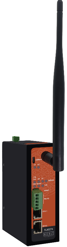
CONNECTORS AND PORTS - LoRa
SMA Antenna Connector for LoRa
1 Standard SMA female interface, 50 ohm
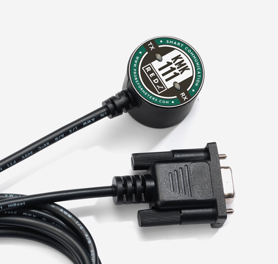
Console Port
USB Type C or Micro USB connection for LOG in 115200 baud
10/100T(X) RJ45 Ports
Ethernet Connection on 2 ports
Serial Ports
5 pin wired Terminal Connection
Tx, Rx, GND for RS232
A, B and GND for RS485
Reset Buttons
Reset to Client and Reset to Server Operating modes buttons
LED INDICATORS
Power Indicator
Power LED
10/100T(X) Indicators
Activity LEDs:
ETH1, ETH2 and Activity of device itself (Marked as device series name, such as CKL/TLM/HUR/LKM)
System Indicators
Status LED,
Tx and Rx of data LEDs and Server LED
Console Indicators
Tx and Rx of data LEDs
POWER - DC
Input Range
5-48V DC wide range power input
(Allows up to 60 V DC)
Reverse Polarity Protection
Available
Thermal Shutdown and Current Limit Protection
Available
PHYSICAL AND ENVIRONMENTAL CHARACTERISTICS - DC POWERED AND BPL MODELS
Enclosure
Metal, IP40
Dimensions
43 x 95 x 124 (w x d x h) mm
Weight
~400gr
Storage Temperature
-65 to 150 °C
Operating Temperature
-40 to 85 °C
Operating Humidity
5% to 95% Non-condensing
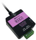
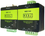
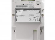
TLM374: 923MHz LoRaWAN EndNode Modem with Modbus TCP/RTU Scheduler, 2x 10/100 T(x) ETH ports, 1 x RS232 & 1 x RS485, 5-48V (max. 60V) DC Power Input