Various types of cookies are used on our website (and on all other digital platforms including mobile applications). View our new THE INFORMATIVE TEXT ON LPPD AND PRIVACY here. Google Analytics Analytical cookies help us to improve our website by collecting and reporting information on its usage. Google AdWords ve Remarketing We use marketing cookies to help us improve the relevancy of advertising campaigns you receive.
I have read the above articles
 INDEX
INDEX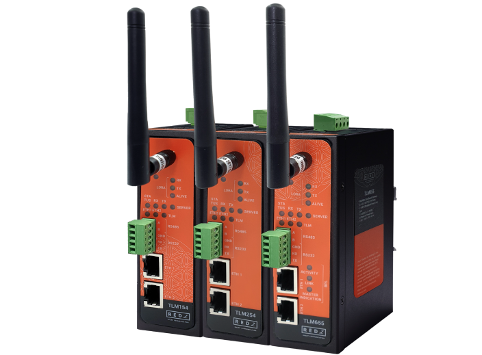
The TLM Series LoRa Radio Modems empowers users to construct a private and efficient wireless network infrastructure. These versatile modems bridge the connectivity gap for field devices by supporting both RS232, RS485 serial and Ethernet communications. By utilizing the LoRa standard, the TLM Series ensures reliable and long-range data transfer over a dedicated radio frequency network, offering a robust solution for challenging operational environments. TLM offers auto network discovery feature to gather signal levels, addresses and configuration/connection lists of all TLM devices in same LoRa RF Network which makes installation easier.
TLM Series LoRa Based RF Modems can act as:
-Transparent Gateway Between TCP Client Devices and LoRa RF Network
-Transparent Gateway Between TCP Server Devices and LoRa RF Network
-Transparent Gateway Between RS232/RS485 Serial Devices and LoRa RF Network
-Modbus TCP to RTU Conversion Gateway for RS232/RS485 Serial Devices for messages over LoRa RF Network
-LoRa Repeater
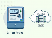
Typical applications: Automated Meter reading, Wireless networks, Home – Building – Industrial Automation, Remote Control, Wireless Sensors, Telemetry, Wireless Alarm and Security Systems…
TLM models with Broadband Power Line (BPL) link can communicate with full transparent TCP/IP standard over Low Voltage power lines and allows easy connection between TCP/IP based terminals without use of extra cables.
TLM Series LoRa Based RF Gateways have the versions with and without BPL (Broadband Power Line ) Link.
Each device has a Din-Rail kit on rear panel. The Din-Rail kit helps device to fix on the Din-Rail. Slant the switch and mount the metal spring to Din-Rail.
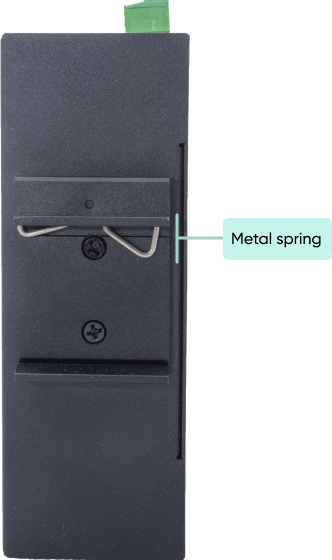
Then Push the switch toward the Din-Rail until you heard a “click” sound.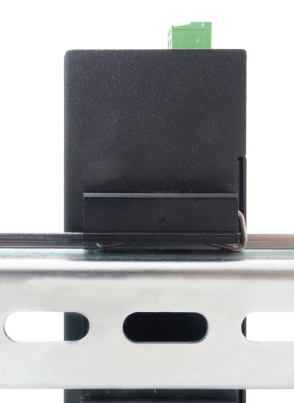
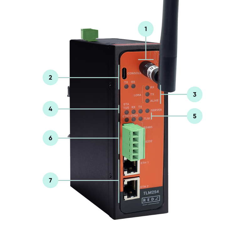

NOTE: TLM194 and TLM294 2.4GHz version has SMA Male Antenna
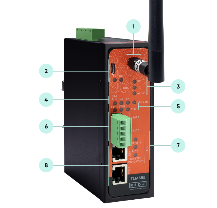
Standard SMA Antenna interface, 50 ohm, female for TLM655 and male for TLM695
NOTE: TLM695 2.4GHz version has SMA Male Antenna
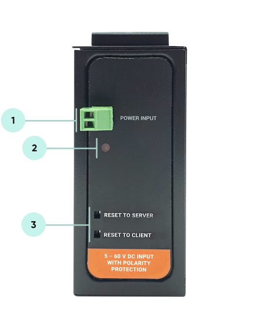
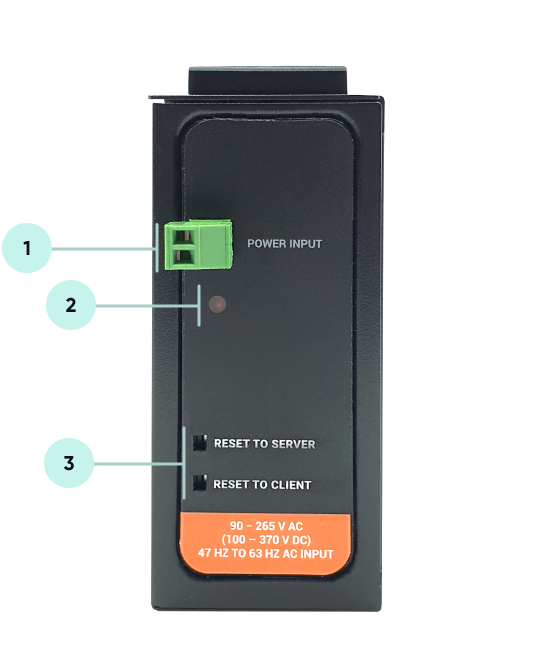
Power Input Options:
AC Power Input 110V–240V/50-60Hz
9-36V DC Power Input
Data Connectivity Options:
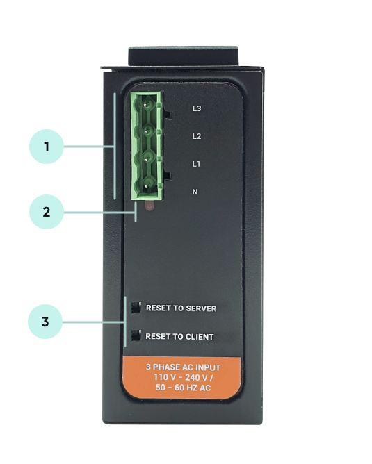
Phase to Phase AC Power Line
Phase to Neutral AC Power Line
DC Power Line
NOTE :
Power Connection
Powering up device is only done over Terminal pins 1 and 2.
Can be purchased in 2 versions:
1. AC Powered version: Device can be powered up with AC input, this option is available in both PN and PP models. It accepts, 110V–240V/50-60Hz. (Power Input can also be used for data transmission in PN Models.)
2. DC Powered version: Device can be powered up with 9-36V DC power. Data transmission only done through terminal pins 3 and 4. This model can be used if DC power source will be used in the field and available with PP or DC model.
Data Connection
Can be purchased in 3 versions:
1. PP Model: Phase to phase model (Standart Model).
Data transmission is only done through terminal pins 3 and 4. AC Phase to phase connection should be done to data transmission pins for better performance. If phase to phase connection is not available then phase and neutral can still be connected for data transmission over terminal pins 3 and 4.
(Ex: L1-L2, L2-L3, L1-L3 or L1-2-3 to N can be used as data connection)
2. PN Model: Phase to neutral model. That version gets power from terminal pins 1 and 2 from phase and neutral and it can also transmit data from that pins (pins 1 and 2). Remaining (pins 3 and 4) pins usage is optional.
(Ex: Master can be connected to all phases and slaves can be connected to relevant phases)
(Ex: L1-N, L2-N, L3-N or L1-2-3 and N can be used as data connection)
3. DC Model: DC data line model. Uses DC Power Line for data transmission. (Ex: 24V+ and GND as data connection)
TLM Series LoRa Based RF Gateways have standard Ethernet ports. According to the link type, the switches use CAT 3, 4, 5, 5e UTP cables to connect to any other network device (PCs, servers, switches, routers, or hubs).
| Cable | Type | Max. Length | Connector |
| 10BASE-T | Cat. 3, 4, 5 100-ohm | UTP 100 m (328 ft) | RJ-45 |
| 100BASE-TX | Cat. 5 100-ohm UTP | UTP 100 m (328 ft) | RJ-45 |
With 100BASE-TX/10BASE-T cable, pins 1 - 2 are used for transmitting data and pins 3 - 6 are used for receiving data.
| Pin Number | Description |
| 1 | TD+ |
| 2 | TD- |
| 3 | RD+ |
| 4 | Not Used |
| 5 | Not Used |
| 6 | RD- |
| 7 | Not Used |
| 8 | Not Used |
| CAT5 Based System | BPL Link Based System | |
| Media | CAT5 | Power Line |
| Bandwidth | 100Mbps | Up to 30Mbps |
| Re-Wire | Yes | No, Using existing Power Line |
| Span | <100m | <600m |
| Multiple Nodes | N/A | Up to 10 hops/1000 nodes |
| Encryption | Yes, but difficult to configure | Yes, Plug & Play |
| Installment | Difficult | Easy, simply user power line |
| Installment Cost | High | Low |
| Total Cost | High | Low |
NOTE :
Power Connection
Powering up device is only done over Terminal pins 1 and 2.
Can be purchased in 2 versions:
1. AC Powered version: Device can be powered up with AC input, this option is available in both PN and PP models. It accepts, 110V–240V/50-60Hz. (Power Input can also be used for data transmission in PN Models.)
2. DC Powered version: Device can be powered up with 9-36V DC power. Data transmission only done through terminal pins 3 and 4. This model can be used if DC power source will be used in the field and available with PP or DC model.
Data Connection
Can be purchased in 3 versions:
1. PP Model: Phase to phase model (Standart Model).
Data transmission is only done through terminal pins 3 and 4. AC Phase to phase connection should be done to data transmission pins for better performance. If phase to phase connection is not available then phase and neutral can still be connected for data transmission over terminal pins 3 and 4.
(Ex: L1-L2, L2-L3, L1-L3 or L1-2-3 to N can be used as data connection)
2. PN Model: Phase to neutral model. That version gets power from terminal pins 1 and 2 from phase and neutral and it can also transmit data from that pins (pins 1 and 2). Remaining (pins 3 and 4) pins usage is optional.
(Ex: Master can be connected to all phases and slaves can be connected to relevant phases)
(Ex: L1-N, L2-N, L3-N or L1-2-3 and N can be used as data connection)
3. DC Model: DC data line model. Uses DC Power Line for data transmission. (Ex: 24V+ and GND as data connection)
TLM Series LoRa Based RF Gateways have 1 x RS232 and 1 xRS485 port. Serial line can be connected other serial devices such as RTUs, PLCs, energy meters or any other field device.
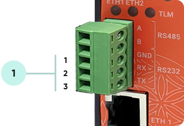
| Pin Number | Description |
| 1 | GND |
| 2 | Rx |
| 3 | Tx |
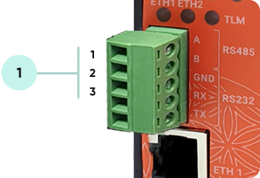
| Pin Number | Description |
| 1 | A |
| 2 | B |
| 3 | GND (Suggested to use) |
Some of the usage scenarios of TLM Series LoRa Based RF Gateways are described below. Usages are not limited to that examples and user may create their own usage scenario. TLM series can be used to connect any serial or ethernet based devices or applications transparently. User may simply think the devices in following examples as TCP/IP or RS232/RS485 serial devices if Modbus protocol is not needed to be used.
TLM Series LoRa Based RF Gateways can link TCP/IP devices and create a network over RF. For example, with TLM Series LoRa Based RF Gateways users can connect Modbus TCP devices such as RTUs or PLCs with each other over RF network and create wireless automation.
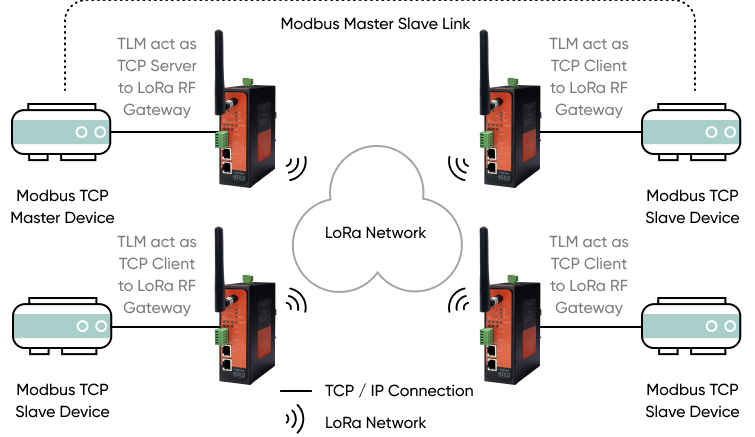
TLM act as TCP Server to LoRa RF Gateway when "Device Function" is configured as "Transparent - LoRa to TCP Server Gateway". Local ETH client device is connected to TLM Server (User must enter TLM IP and TLM Server Listening port in local device). LoRa communication configuration must be same along the LoRa network. TLM will send LoRa packages to configured Tx Group Address + Tx Device Address combination. User may define 0xFF and 0xFFFF for broadcasting (send LoRa packages to all LoRa devices in LoRa Network). TLM will get LoRa packages from Group Address + Device Address combination and user may keep as default: 0x01 and 0x0001.
TLM act as TCP Client to LoRa RF Gateway when "Device Function" is configured as "Transparent - LoRa to TCP Client Gateway". TLM can automatically connect field devices that are accepting TCP connections on their Modbus TCP port. In that case, field device IP and port must be configured in TLM. LoRa communication configuration must be same along the LoRa network. TLM will send LoRa packages to configured Tx Group Address + Tx Device Address combination. User may define 0x01 and 0x0001 for sending packages back only to TLM connected to Modbus TCP Master device.
TLM Series LoRa Based RF Gateways can link RS232 and/or RS485 serial devices and create a network over RF. For example, with TLM Series LoRa Based RF Gateways users can connect RS232 and/or RS485 Modbus RTU/ASCII devices such as RTUs or PLCs with each other over RF network and create wireless automation.
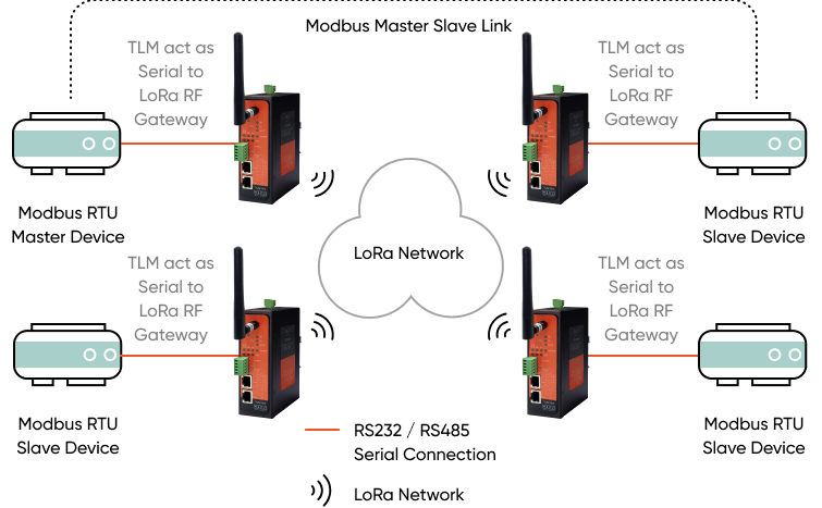
TLM act as Serial to LoRa RF Gateway when "Device Function" is configured as "Transparent - LoRa to SERIAL Gateway". Serial communication is enabled and settings are done based on field device. LoRa communication configuration must be same along the Lora network. TLM will send LoRa packages to configured Tx Group Address + Tx Device Address combination. User may define 0xFF and 0xFFFF for broadcasting (send LoRa packages to all LoRa devices in LoRa Network). TLM will get LoRa packages from Group Address + Device Address combination and user may keep as default: 0x01 and 0x0001.
TLM Series LoRa Based RF Gateways can link RS232 and/or RS485 Modbus RTU field serial devices and create a network over RF and serial devices can receive and send data to a Modbus TCP server ( or Modbus TCP field devices). The communication works bidirectionally. For example, with TLM Series LoRa Based RF Gateways users can connect Modbus TCP devices such as RTUs or PLCs and also RS232 and/or RS485 Modbus RTU devices with each other over RF network and create wireless automation for both Modbus TCP and RTU protocol devices..
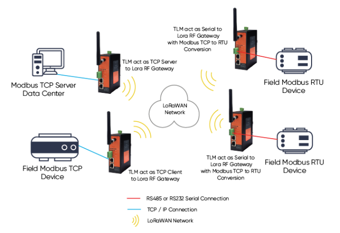
Master TLM act as TCP Server to LoRa RF Gateway when "Device Function" is configured as "Transparent - LoRa to TCP Server Gateway". Local ETH client device is connected to TLM Server (User must enter TLM IP and TLM Server Listening port in local device). LoRa communication configuration must be same along the LoRa network. TLM will send LoRa packages to configured Tx Group Address + Tx Device Address combination. User may define 0xFF and 0xFFFF for broadcasting (send LoRa packages to all LoRa devices in LoRa Network). TLM will get LoRa packages from Group Address + Device Address combination and user may keep as default: 0x01 and 0x0001.
Slave TLMs act as Serial to LoRa RF Gateway with ModbusTCP to RTU vonversion when "Device Function" is configured as "LoRa to Serial Device Gateway with Modbus TCP/RTU Conversion". Serial communication is enabled and settings are done based on field device. LoRa communication configuration must be same along the Lora network. TLM will send LoRa packages to configured Tx Group Address + Tx Device Address combination. User may define 0x01 and 0x0001 for sending back to Master TLM device. TLM will get LoRa packages from Group Address + Device Address combination and user may keep group as default: 0x01 and change device address 0x0002 or another one which should be different for all TLM devices in same LoRa Network.
TLM Series LoRa Based RF Gateways can link 2 different RF network over TCP/IP LAN or WAN network. This helps to extend RF network without distance limit. Communication works bidirectionally. For example, with TLM Series LoRa Based RF Gateways users can connect Modbus TCP devices such as RTUs or PLCs with each other over 2 different RF network and create wireless automation between each other.
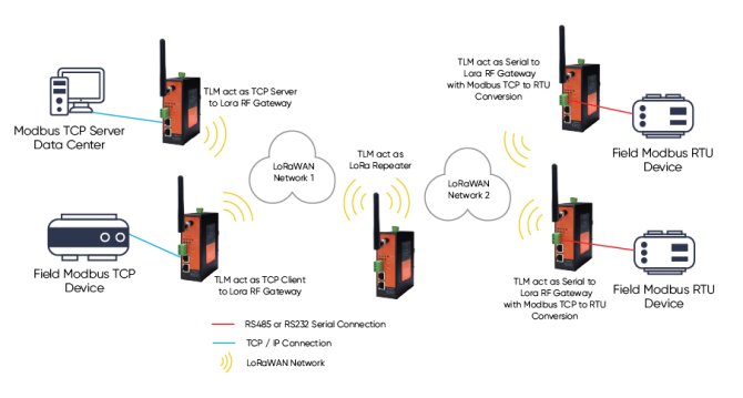
TLM act as LoRa Repeater when "Device Function" is configured as "LoRa Repater". TLM will listen all LoRa packages in LoRa network and resends it again to LoRa configured network settings (Tx Group Address + Tx Device Address combination). User may define 0x01 and 0xFFFF for broadcasting (send LoRa packages to all LoRa devices in LoRa Network 1). Also, user may define 0x02 and 0x0001 for sending packages back only to TLM connected to Modbus TCP Master device in Network 2. The configuration may change depending on actual usage case.
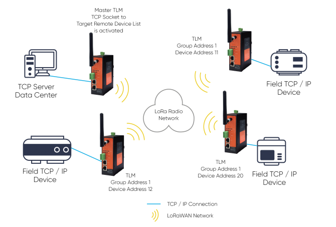
TLM Series LoRa Based RF Gateways can link TCP/IP devices and create a Radio network. In standart usage point to multipoint connection uses broadcasting the data and receiving the response only to master TLM device. This needs an address based protocol running on Radio network. However if TCP Socket to Target Remote Device List is activated, Master TLM can send all data from specified socket to specified target device when "Device Function" is configured as "Transparent - LoRa to TCP Server Gateway" and "Enable TCP Socket to Target Device Matching List" is enabled.
Master TLM is set to TCP Server Mode and (probably) transparent Operation Mode is selected since the protocol planned to be used has no address based control (Modbus has address based control). User then can list the mapping as follows
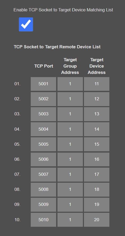
Then if an application connect TLM from socket 5001, all data received will be sent to TLM with Group Address 1 and Device Address 11. In same manner if an application connect TLM from socket 5010, all data received will be sent to TLM with Group Address 1 and Device Address 20. User can change the Group Addresses and Device Addresses or TCP Sockets freely.
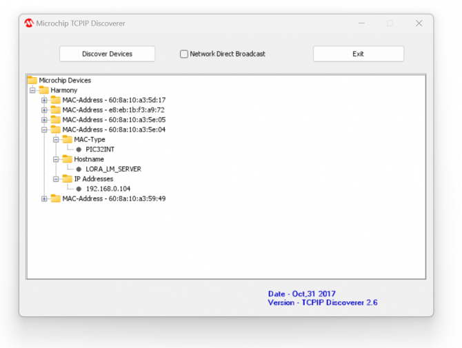
TLM Series LoRa RF Modems can be configured over web interface.
Device will get IP from DHCP client when connected to a network. User can use discovery tool to see IP of the device.

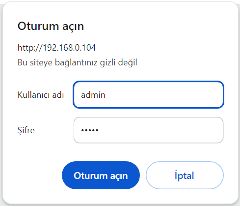
Once the IP of the device is set, user may login the device by simply typing the Ip address of device.
NOTE 1: TLM default firmware runs with DHCP off and expects an IP lease. If user needs static IP or prefers DHCP on during start up, it can easily be configured from the the web interface.
NOTE 2: If there is no DHCP server in LAN, REDZ device will get default 192.168.1.1
Simply write IP of the device to the http client. Login screen will pop up.
Default user name: admin
Default password: admin
Main screen of device will appear with following information:
Firmware Info, MAC details and Device Name on top
Menu Items on left
Menu Item details in center
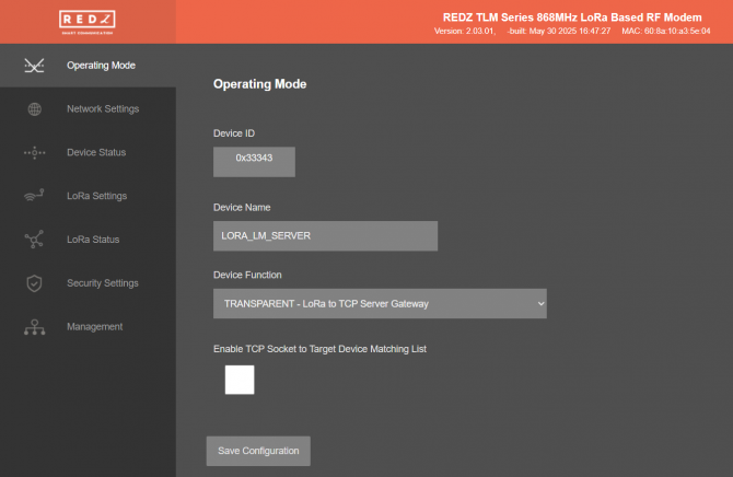
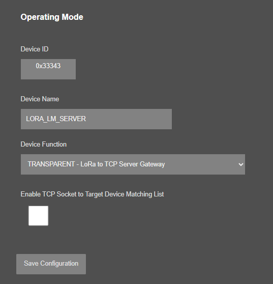
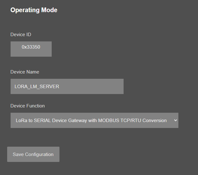
From this menu user may select the operating mode of the device.
TLM is 1 Device with 5 different Gateway Operating Modes:
TLM can create following networks:
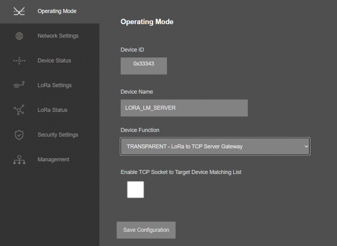
“Device ID” field is the unique Device ID of TLM device itself, based on LoRa Module serial number.
“Device Name” field is used to identify device.
“Device Function” field is used to select device behaviour.
“TRANSPARENT - LoRa to TCP Server Gateway”, “TRANSPARENT - LoRa to TCP Client Gateway” or “TRANSPARENT - LoRa to SERIAL Gateway”: If "TRANSPARENT" selected, then all data received from LoRa side will be sent to Gateway side (TCP or Serial based on user settings) as it is.
“LoRa to Serial Device Gateway with Modbus TCP/RTU Conversion”: If "Modbus TCP to RTU" is selected, then all data received from LoRa side will be sent to Serial side by converting Modbus TCP package to Modbus RTU format. It can only be used for Modbus protocol.
“LoRa Repeater”: If "Repeater" function is selected then the device will listen LoRa Packages that is targeted to its address adn repeates it to configured Group and Device Address ( ex: broadcast address).
“Enable TCP Socket to Target Device Matching List” is used for enabling or disabling TCP socket to Remote Target Device list and available when "Device Function" is set to “TRANSPARENT - LoRa to TCP Server Gateway”. TLM Series LoRa Based RF Gateways can link TCP/IP devices and create a Radio network. In standart usage point to multipoint connection uses broadcasting the data and receiveng the response only to master TLM device. This needs an address based protocol running on Radio network. However if TCP Socket to Target Remote Device List is activated, Master TLM can send all data from specified socket to specified target device.
Master TLM is set to TCP Server Mode and transparent Operation Mode is selected since the protocol planned to be used has no address based control (Modbus has address based control). User then can list the mapping as follows:

Then if an application connect TLM from socket 5001, all data received will be sent to TLM with Group Address 1 and Device Address 11. In same manner if an application connect TLM from socket 5010, all data received will be sent to TLM with Group Address 1 and Device Address 20. User can change the Group Addresses and Device Addresses or TCP Sockets freely.
When "Device Function" is set to “TRANSPARENT - LoRa to TCP Client Gateway”, following screen will be available to configure target TCP/IP devices.
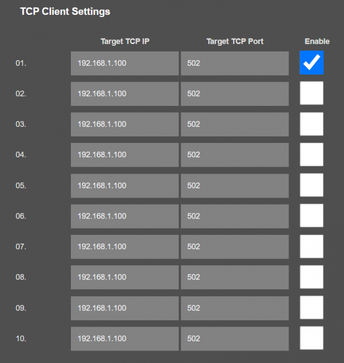
"Target TCP IP": Static TCP IP address of the remote/local TCP Device that the TLM will connect.
"Target TCP Port": TCP IP port of the remote/local TCP Device that the TLM will connect.
"Enable": Enable remote device connection to let TLM connect the remote TCP/IP device automatically. At least 1 remote device must be enabled. Maximum 10 remote devices can be connected.
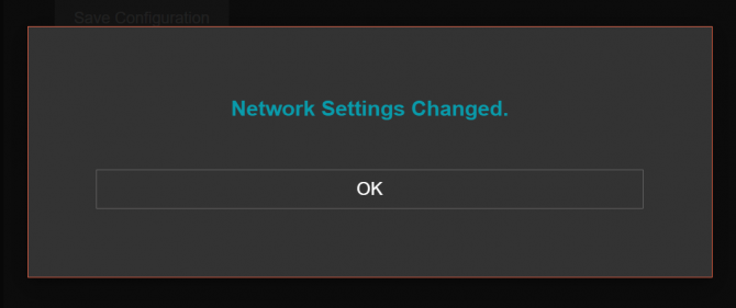
When all settings done, click "Save Configuration" to save settings.

After clicking button system will tell if the settings applied successfully or not.
NOTE: Settings will be applied once the device is rebooted from web interface or repowered manually.
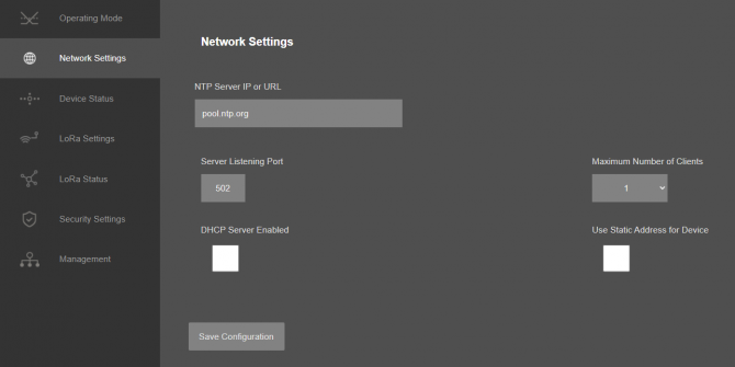
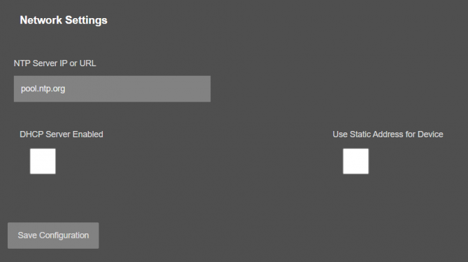
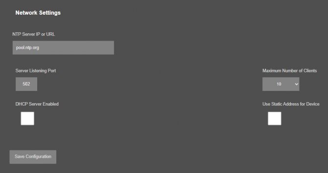
From this menu user may change the network settings of the device.
NOTE:
NTP is only used to syncronize device time after a manual or system triggered restarts and it only takes place if NTP time is available and device time difference from NTP time is + or - 24 Hours.
Also following options are available when "Device Function" is set to “TRANSPARENT - LoRa to TCP Server Gateway”.
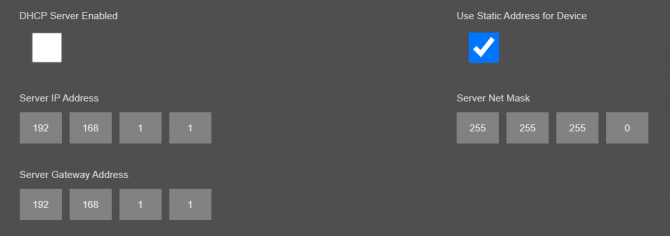
Following parameters and static IP settings available if “Use Static Address for Device” checked.
"Listening Port": TCP Port that TLM uses for incoming connections. Remote devices can use TLM IP and this port to connect to TLM for Radio communication. Available when "Device Function" is set to “TRANSPARENT - LoRa to TCP Server Gateway”.
"Maximum Number of Clients": Maximum numbers of incoming connections accepted. TLM can accept up to 10 simultaneous connection and all devices can send TCP data to Radio network. Available when "Device Function" is set to “TRANSPARENT - LoRa to TCP Server Gateway”.
"Use Static Address for Device": Set a static TCP IP for TLM from this part. Enable and enter network settings and TLM will be available to connect from this static IP locally or remotely (gateway must be set properly for remote WAN connection).
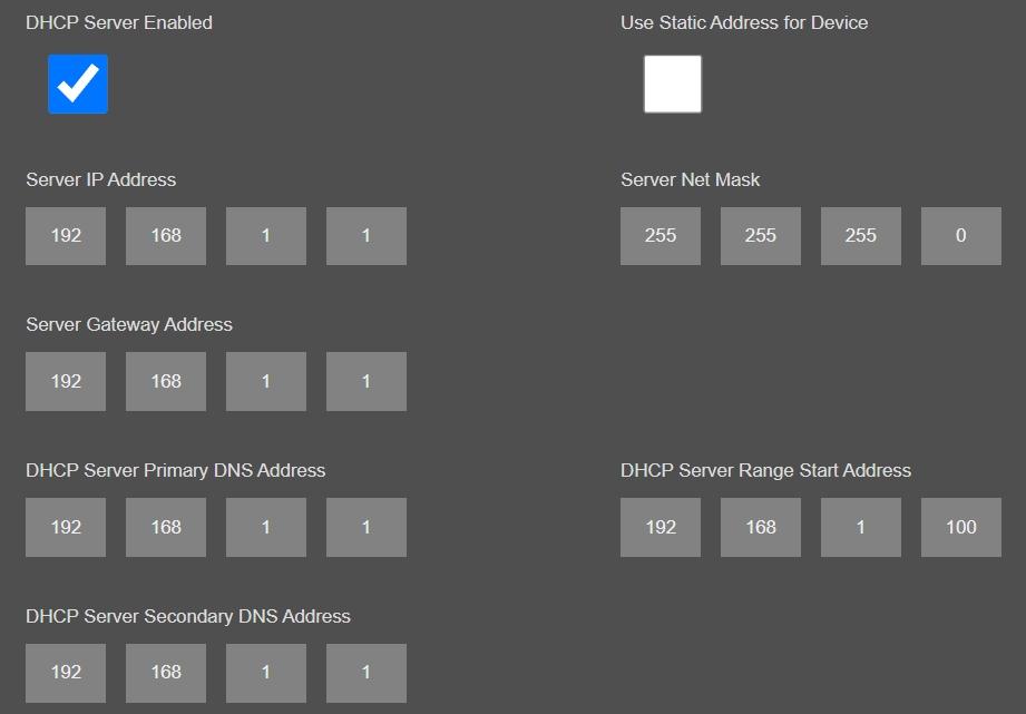
Following parameters available if “DHCP Server” setting is enabled. This is used if DHCP server is needed in network. TLM can distribute IP to field devices connected to it in this way.
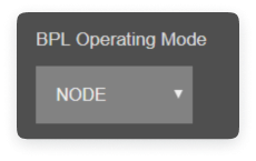
Also if the device has Broadband Power Line (BPL) option:
User can select operating mode of BPL either MASTER or NODE.
NOTE: Standard firmware of REDZ BPL supports up to 10 hops and 1000 nodes. Only 1 device can be MASTER in same network.
Once the setting has been changed, “Save Configuration” button will be enabled.
After clicking button system will tell if the settings applied successfully or not.
NOTE 1: Settings will be applied once the device is rebooted from web interface or repowered manually.
NOTE 2: If "Device Function" is NOT set to “TRANSPARENT - LoRa to TCP Server Gateway” and set to any other option, only following menu items will be available on this menu.
NOTE: This menu item is only available when "Device Function" is set to “TRANSPARENT - LoRa to SERIAL Gateway” or “LoRa to Serial Device Gateway with Modbus TCP/RTU Conversion”.
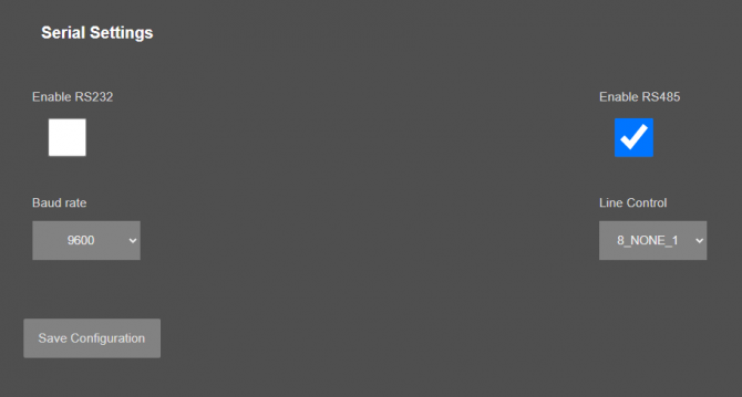
From this menu user may activate RS232 or RS485 connection as serial physicall connection.
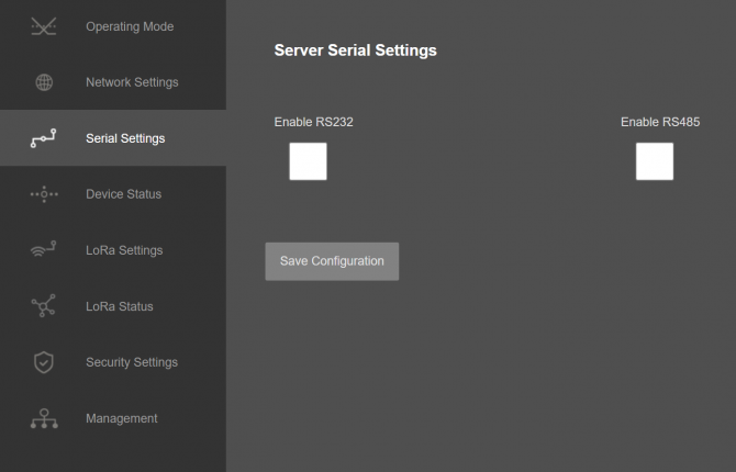
Following settings are available for serial line.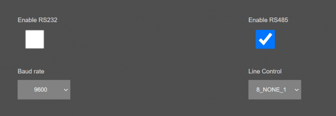
"Baud rate": Serial communication baud rate selection.
"Line Control": Serial communication data type selection in form of Data bits-Parity-Stop bits. Available options are:
7_EVEN_1 (Not used in Modbus)
8_NONE_1
9_NONE_1
8_EVEN_1
8_EVEN_2
8_ODD_1
8_ODD_2
8_NONE_2
9_NONE_2
Once the setting has been changed, “Save Configuration” button will be enabled.

After clicking button system will tell if the settings applied successfully or not.
NOTE : Settings will be applied once the device is rebooted from web interface or repowered manually.
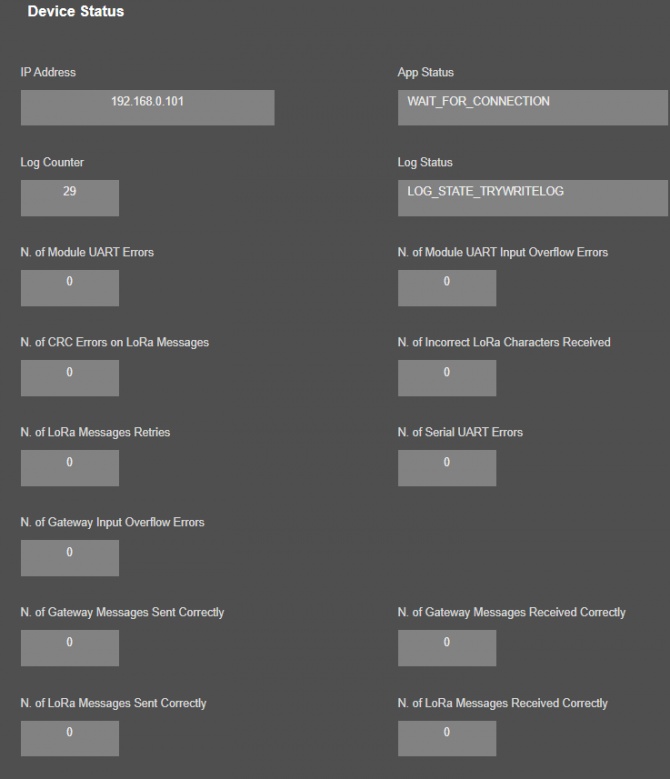
From this menu user may monitor device status and statistics based on operating mode of device. The page also helps users to check device health and communication details.
NOTE: This menu details change based on selected "Device Function".
Here are menu options when "Device Function" is set to “TRANSPARENT - LoRa to TCP Server Gateway” or “TRANSPARENT - LoRa to TCP Client Gateway”.
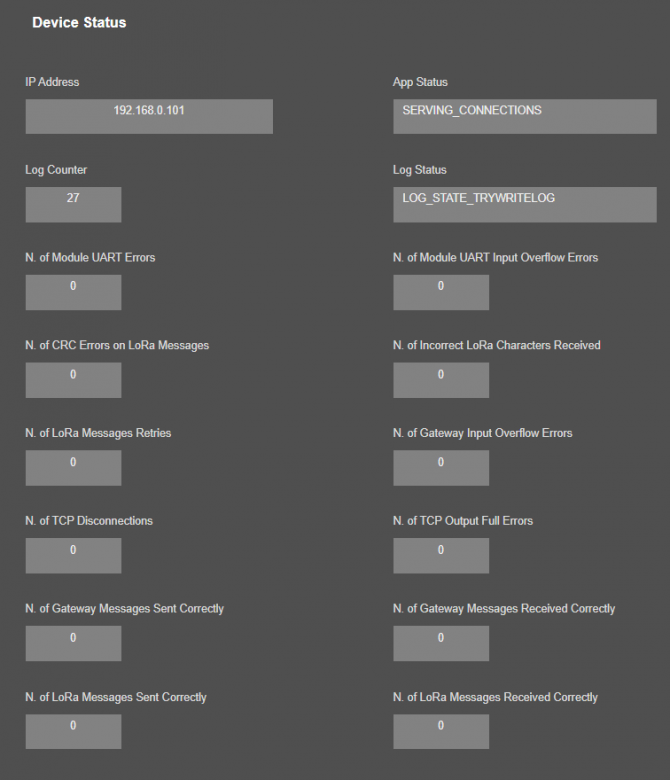
"IP Address": TCP/IP address of TLM itself.
"App Status": It shows current status of TLM application. "SERVING CONNECTIONS" means device is ready for normal operation.
"Log Status": It is only available when "Log" is enabled from "Management" menu and shows current status of TLM logging. "LOG_STATE_TRYWRITELOG" means normal operation.
"Log Counter": It is only available when "Log" is enabled from "Management" menu and shows how many log lines has been transfered till now.
"N. of Module UART Errors": Number of module uart errors. Device will enter "Reboot State" if this number is above 20.
"N. of Module UART Input Overflow Errors": Number of module input overflow errors.
"N. of CRC Errors on LoRa Messages": Number of CRC errors during getting LoRa packages.
"N. of Incorrect LoRa Characters Received": Number of Incorrect characters received during getting LoRa packages.
"N. of LoRa Messages Retries": Number of LoRa messages send trials due to failure of sending the message.
"N. of Gateway Input Overflow Errors": Number of Serial side input overflow errors both on RS232 and RS485 or TCP side input overflow errors based on TLM gateway settings.
"N. of TCP Disconnections": Number of TCP disconnections from TLM. Not available if one of serial line is enabled.
"N. of TCP Output Full Errors": Number of TCP output full errors during trying to send data to TCP side. Device will enter "Reboot State" if this number is above 5. Not available if one of serial line is enabled.
"N. of Gateway Messages Sent Correctly": Number of data packages sent to Serial RS232 and RS485 side or TCP side based on TLM gateway settings.
"N. of Gateway Messages Received Correctly": Number of data packages received from Serial RS232 and RS485 side or TCP side based on TLM gateway settings.
"N. of LoRa Messages Sent Correctly": Number of LoRa packages sent to LoRa Radio Network successfully.
"N. of LoRa Messages Received Correctly": Number of LoRa packages received successfully over the LoRa Radio Network.
In "TCP Connections" part when Device Function is set to “TRANSPARENT - LoRa to TCP Server Gateway”:
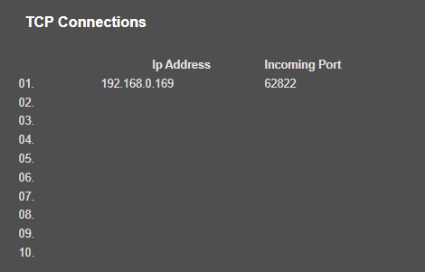
Device can show up to 10 lines in this part based on "Maximum Number of Clients" setting under "Network Settings" Menu.
"Ip Address": Is the TCP IP address of client connected to TLM.
"Incoming Port": Is the TCP Port of socket used by client connected to TLM.
In "TCP Client Status" part when Device Function is set to “TRANSPARENT - LoRa to TCP Client Gateway”:
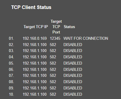
"Target TCP IP": Shows the configured static TCP IP for the remote/local TCP/IP device
"Target TCP Port": Shows the configured TCP port for the remote/local TCP/IP device
"Status": Shows connection status of remote/local device. Following status values are available:
"CONNECTED": connected to remote/local TCP/IP device.
"WAIT FOR CONNECTION": Device is reachable and TLM is trying to open TCP/IP connection.
"OPENING CONNECTION": TLM will check TCP/IP connection if the remote/local TCP/IP device is reachable.
"HOST UNREACHABLE": Remote/local TCP/IP device is not reachable ( ex: not in LAN/WAN network)
"DISABLED": This connection is not enable and TLM will not check.
Here are menu options when "Device Function" is set to “TRANSPARENT - LoRa to SERIAL Gateway” or “LoRa to Serial Device Gateway with Modbus TCP/RTU Conversion”.
"IP Address": TCP/IP address of TLM itself.
"App Status": It shows current status of TLM application. "SERVING CONNECTIONS" means device is ready for normal operation.
"Log Status": It is only available when "Log" is enabled from "Management" menu and shows current status of TLM logging. "LOG_STATE_TRYWRITELOG" means normal operation.
"Log Counter": It is only available when "Log" is enabled from "Management" menu and shows how many log lines has been transfered till now.
"N. of Module UART Errors": Number of module uart errors. Device will enter "Reboot State" if this number is above 20.
"N. of Module UART Input Overflow Errors": Number of module input overflow errors.
"N. of CRC Errors on LoRa Messages": Number of CRC errors during getting LoRa packages.
"N. of Incorrect LoRa Characters Received": Number of Incorrect characters received during getting LoRa packages.
"N. of LoRa Messages Retries": Number of LoRa messages send trials due to failure of sending the message.
"N. of Serial UART Errors": Number of serial uart errors. Device will enter "Reboot State" if this number is above 20.
"N. of Gateway Input Overflow Errors": Number of Serial side input overflow errors both on RS232 and RS485 or TCP side input overflow errors based on TLM gateway settings.
"N. of Gateway Messages Sent Correctly": Number of data packages sent to Serial RS232 and RS485 side or TCP side based on TLM gateway settings.
"N. of Gateway Messages Received Correctly": Number of data packages received from Serial RS232 and RS485 side or TCP side based on TLM gateway settings.
"N. of LoRa Messages Sent Correctly": Number of LoRa packages sent to LoRa Radio Network successfully.
"N. of LoRa Messages Received Correctly": Number of LoRa packages received successfully over the LoRa Radio Network.
When Device Function is set to “LoRa to Serial Device Gateway with Modbus TCP/RTU Conversion”:
TLM will show additional value:
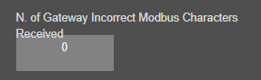
"N. of Gateway Incorrect Modbus Characters Received": Number of Incorrect characters received during getting Modbus packages.
Here are menu options when "Device Function" is set to “LoRa Repeater”.

"IP Address": TCP/IP address of TLM itself.
"App Status": It shows current status of TLM application. "SERVING CONNECTIONS" means device is ready for normal operation.
"Log Status": It is only available when "Log" is enabled from "Management" menu and shows current status of TLM logging. "LOG_STATE_TRYWRITELOG" means normal operation.
"Log Counter": It is only available when "Log" is enabled from "Management" menu and shows how many log lines has been transfered till now.
"N. of Module UART Errors": Number of module uart errors. Device will enter "Reboot State" if this number is above 20.
"N. of Module UART Input Overflow Errors": Number of module input overflow errors.
"N. of CRC Errors on LoRa Messages": Number of CRC errors during getting LoRa packages.
"N. of Incorrect LoRa Characters Received": Number of Incorrect characters received during getting LoRa packages.
"N. of LoRa Messages Sent Correctly": Number of LoRa packages sent to LoRa Radio Network successfully.
"N. of LoRa Messages Received Correctly": Number of LoRa packages received successfully over the LoRa Radio Network.

After clicking “Refresh Status” button, system will reload data only and will not reload page. Button will be disabled during reload for an instance. If timeout occurs during the reload, the button will be enabled again with warning of timeout. In normal operation reload of status data will be done immediately. "Reset Logs" button will reset device status parameres.
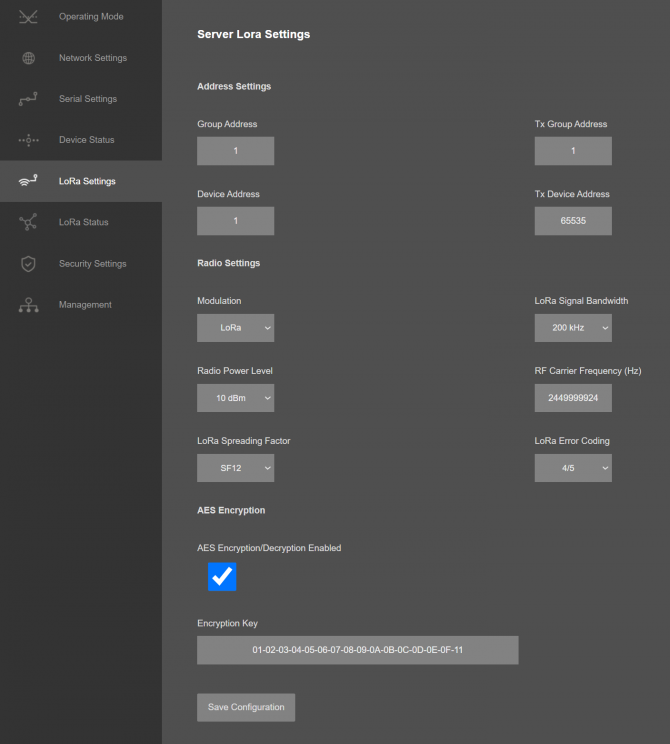
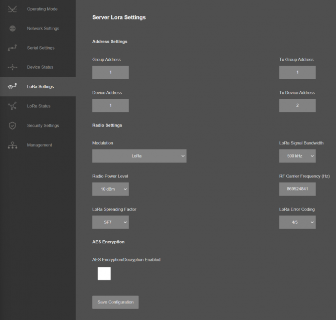
From this menu user may change LoRa RF parameters.
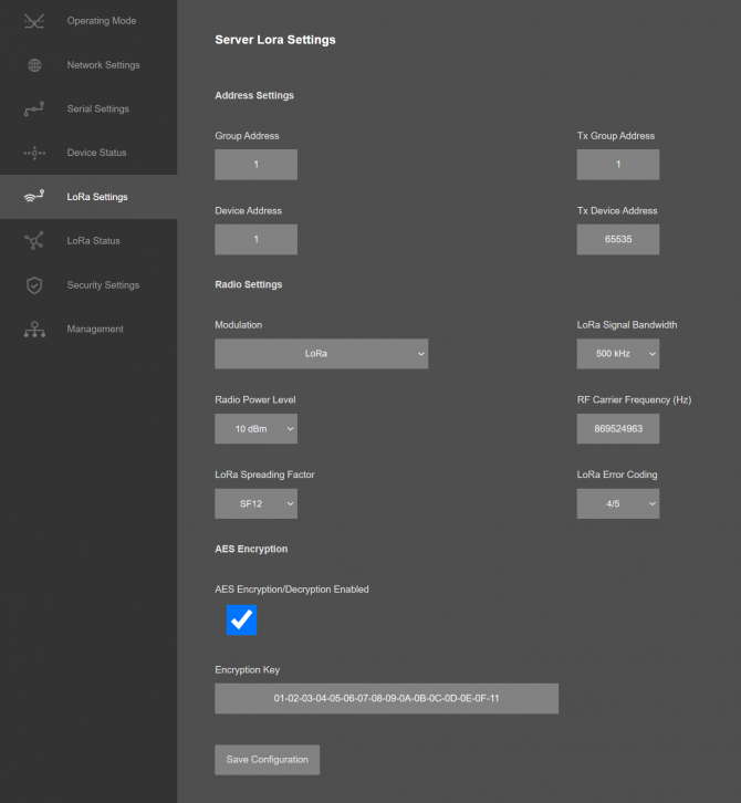
TLM uses Semtech’s patented LoRa modulation technique which combines spread spectrum modulation and forward error correction techniques to increase the range and robustness of radio communication links compared with traditional FSK or OOK based modulation. Typically examples of TLM receive performances are given in the following table.
| Signal Bandwidth/[kHz] | Spreading Factor | Sensitivity/[dBm] |
| 125 | 7 | -123 |
| 125 | 12 | -138 |
| 250 | 7 | -121 |
| 250 | 12 | -135 |
| 500 | 7 | -116 |
| 500 | 12 | -130 |
TLM uses Semtech’s LoRa proprietary spread spectrum modulation technique. This modulation, in contrast to conventional modulation techniques, permits an increase in link budget and increased immunity to in-band interference. It achieves sensitivities 8 dB better than FSK modulation.
LoRa also provides significant advantages in both blocking and selectivity, solving the traditional design compromise between range, interference immunity and energy consumption.
TLM offers three bandwidth options of 125 kHz, 250 kHz, and 500 kHz with spreading factors ranging from 7 to 12.
The spread spectrum LoRa modulation is performed by representing each bit of payload information by multiple chips of information. The rate at which the spread information is sent is referred to as the symbol rate (Rs), the ratio between the nominal symbol rate and chip rate is the spreading factor and represents the number of symbols sent per bit of information. The range of parameters which can be configured are given in the following tables.
| Spreading Factor | Chips/Symbol | SNR/[dB] |
| 7 | 128 | -7,5 |
| 8 | 256 | -10 |
| 9 | 512 | -12,5 |
| 10 | 1024 | -15 |
| 11 | 2048 | -17,5 |
| 12 | 4096 | -20 |
Note that the spreading factor must be known in advance on both transmit and receive sides of the radio link as different spreading factors are orthogonal to each other. Note also the resulting signal to noise ratio (SNR) required at the receiver input. It is the capability to receive signals with negative SNR that increases the sensitivity, so link budget and range, of the LoRa receiver.
To further improve the robustness of the radio link, TLM provides cyclic error coding with different coding rates. With using this coding scheme forward error detection and correction can be applied.
| Coding Rate | Chips/Symbol | Overhead Ratio |
| 1 | 4/5 | 1,25 |
| 2 | 4/6 | 1,5 |
| 3 | 4/7 | 1,75 |
| 4 | 4/8 | 2 |
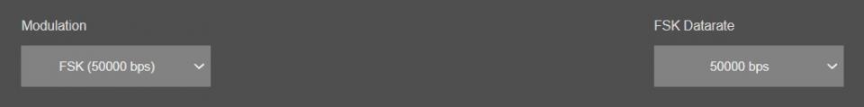
Following parameters are available for “FSK” modulation.
Data Rate can be selected as 50000, 100000 or 250000bps.
Once the setting has been changed, “Save Configuration” button will be enabled.
After clicking button system will tell if the settings applied successfully or not.
NOTE: Settings will be applied once the device is rebooted from web interface or repowered manually.
From this menu user may change LoRa RF parameters.
TLM uses Semtech’s patented LoRa modulation technique well as FLRC (Fast Long Range Communication) which combines spread spectrum modulation and forward error correction techniques to increase the range and robustness of radio communication links compared with traditional FSK or OOK based modulation. Typically examples of TLM receive performances are given in the following table.
| Signal Bandwidth/[kHz] | Spreading Factor | Sensitivity/[dBm] |
| 203 | 5 | -109 |
| 203 | 12 | -130 |
| 406 | 5 | -105 |
| 406 | 12 | -127 |
| 812 | 5 | -103 |
| 812 | 12 | -126 |
| 1625 | 5 | -99 |
| 1625 | 12 | -120 |
TLM uses Semtech’s LoRa proprietary spread spectrum modulation technique. This modulation, in contrast to conventional modulation techniques, permits an increase in link budget and increased immunity to in-band interference.
LoRa also provides significant advantages in both blocking and selectivity, solving the traditional design compromise between range, interference immunity and energy consumption.
TLM offers four bandwidth options of 203 kHz, 406 kHz, 812 kHz and 1,625 kHz with spreading factors ranging from 5 to 12.
The spread spectrum LoRa modulation is performed by representing each bit of payload information by multiple chips of information. The rate at which the spread information is sent is referred to as the symbol rate (Rs), the ratio between the nominal symbol rate and chip rate is the spreading factor and represents the number of symbols sent per bit of information. The range of parameters which can be configured are given in the following tables.
| Spreading Factor | Chips/Symbol | SNR/[dB] |
| 5 | 32 | Tbd |
| 6 | 64 | Tbd |
| 7 | 128 | Tbd |
| 8 | 256 | Tbd |
| 9 | 512 | Tbd |
| 10 | 1024 | Tbd |
| 11 | 2048 | Tbd |
| 12 | 4096 | Tbd |
Note that the spreading factor must be known in advance on both transmit and receive sides of the radio link as different spreading factors are orthogonal to each other. Note also the resulting signal to noise ratio (SNR) required at the receiver input. It is the capability to receive signals with negative SNR that increases the sensitivity, so link budget and range, of the LoRa receiver.
To further improve the robustness of the radio link, TLM provides cyclic error coding with different coding rates. With using this coding scheme forward error detection and correction can be applied.
| Coding Rate | Chips/Symbol | Overhead Ratio |
| 1 | 4/5 | 1,25 |
| 2 | 4/6 | 1,5 |
| 3 | 4/7 | 1,75 |
| 4 | 4/8 | 2 |
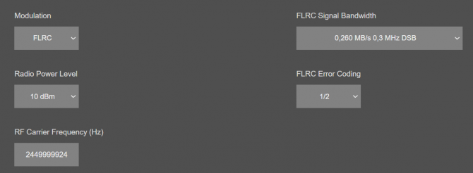
Following parameters are available for “FLRC” modulation.
Data Rate can be selected between 0,260 MB/s to 1,300 MB/s
Once the setting has been changed, “Save Configuration” button will be enabled.
After clicking button system will tell if the settings applied successfully or not.

NOTE: Settings will be applied once the device is rebooted from web interface or repowered manually.
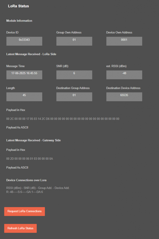
From this menu user may monitor LoRa status and package details. Package from gateway side comes from either TCP/IP or RS232/RS485 serial line based on operating mode of device.
The page also helps users to diagnose radio communication health and see avilable devices in LoRa network.
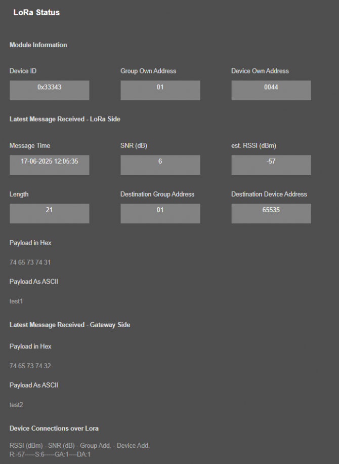
"Message Time": Device time when the message received.
"SNR (dB)": SNR value of the received message in dB.
"est. RSSI (dBm)": Estimated RSSI value of the received message in dBm.
"Length": Package length in bytes of the received message.
"Destination Group Address": The target group address of the received message. User may see from this value if received message is a broadcast message or not.
"Destination Device Address": The target device address of the received message. User may see from this value if received message is a broadcast message or not.
"Payload in Hex": TLM will show the received message as Hexadecimal bytes in this part. This can be used for diagnostic purposes and to confirm if the package received correctly from LoRa Radio Network.
"Payload in ASCII": TLM will show the received message as ASCII characters in this part. This can be used for diagnostic purposes and to confirm if the package received correctly from LoRa Radio Network.
In "Latest Message Received - Gateway Side" part:
"Payload in Hex": TLM will show the received message as Hexadecimal bytes in this part. This can be used for diagnostic purposes and to confirm if the package received correctly from LoRa Radio Network.
"Payload in ASCII": TLM will show the received message as ASCII characters in this part. This can be used for diagnostic purposes and to confirm if the package received correctly from LoRa Radio Network.
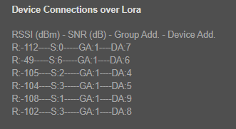
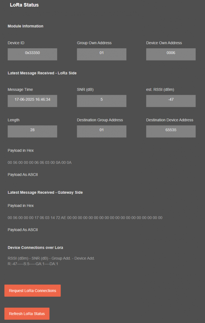
In "Device Connections over Lora" part:
TLM will show RSSI value - SNR value - Group Address - Device Address of all devices that it is already in communication.
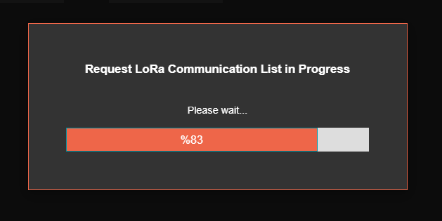
When the "Request LoRa Connections" button clicked, TLM will initiate the discovery process for all devices available for communication in same LoRa Network.

It will show the progress on screen.
Once finished, TLM will show a more detailed list with RSSI value - SNR value - Group Address - Device Address of all devices that it is already in communication as well as Device Ids and Device Details.
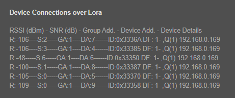
In device details part, TLM shows the "Defice Function" of other TLMs in LoRa Network, here are explanations of numbers:
1: “TRANSPARENT - LoRa to TCP Server Gateway”
2: “TRANSPARENT - LoRa to TCP Client Gateway”
3: “TRANSPARENT - LoRa to SERIAL Gateway”
4: “LoRa to Serial Device Gateway with Modbus TCP/RTU Conversion”
5: “LoRa Repeater”
Also if it is 1 (“TRANSPARENT - LoRa to TCP Server Gateway”) or 2 (“TRANSPARENT - LoRa to TCP Client Gateway”), it will show the connected IP list.

After clicking “Refresh LoRa Status” button, system will reload data only and will not reload page. Button will be disabled during reload for an instance. If timeout occurs during the reload, the button will be enabled again with warning of timeout. In normal operation reload of status data will be done immediately.
From this menu user may activate LoRa RF communication package filter based on White list (accepted packages from Rx Address) or Black list ( rejected packages from Rx Address).
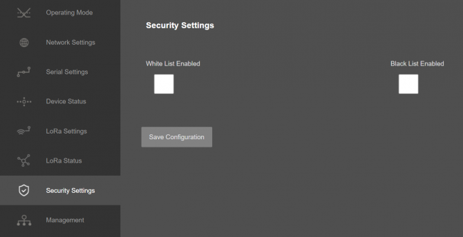
Following settings are available for any of the list.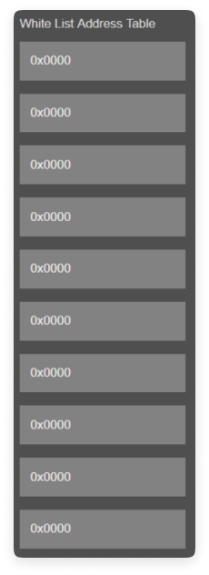
In this page user can enter decimal values and page will format it to hexadecimal automatically after cursor is moved out of scope.

Once the setting has been changed, “Save Configuration” button will be enabled.
After clicking button system will tell if the settings applied successfully or not.
NOTE : Settings will be applied once the device is rebooted from web interface or repowered manually.
From this menu user may change parameters or send command to device
The device restarts itself every 86400 seconds (which means every 24 hours). There are also timeout restart routines in TCP Server mode during listening clients and in Client Mode trying to connect to the TCP server. ( both preset to 10 minutes which means device will restart system if fails to connect a server in Client mode or a client do not connect in preset time in Server mode)
NOTE: NTP is only used to syncronize device time after a manual or system triggered restarts and it only takes place if NTP time is available and device time difference from NTP time is + or - 24 Hours.
After a firmware change old configuration will be used for minor changes. If a major change occurs system will restore to factory default configuration.
User can change the login information.
User can change the debug level of the device. REDZ TLM LoRa Based RF Gateways series has micro USB and gives log in 115200 - 8N1 format.
Any terminal program can be used to listen the LOG over USB type-C or micro USB port of the device which is recognized as Virtual COM port in PC.
LOG to remote UDP server is also available. If set to UDP server, then LKM will send LOG data to remote UDP server device.
User can restore to factory settings and force device to reboot. Factory settings restored by clicking "Restore Factory Configuration" button.
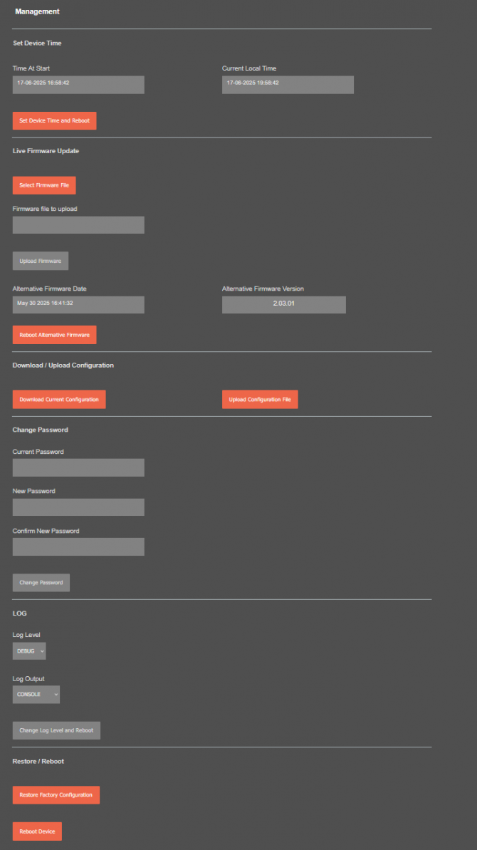
In "Live Firmware Update" part:
Firmware upgrade is possible only with files that REDZ supplied. Once the file selected, TLM shows selected file: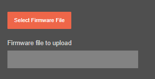
Then “Upload Firmware” button must be clicked. TLM will start to upload file and show status on pop up screen.
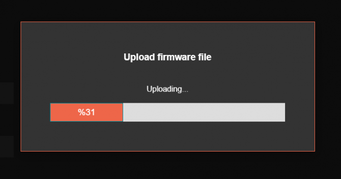
Click "Close" when finished. If somehow LKM fails to upload, refresh webpage and try again please.
After successful upload, TLM will show "Alternative Firmware Date" and "Alternative Firmware Version" data.
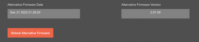
Click "Reboot Alternative Firmware" and TLM will reboot with new firmware and show status on screen.
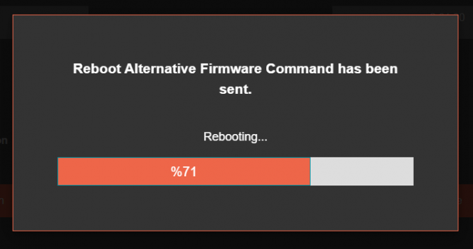
This will take 5 seconds only. Please wait .
Check firmware details from upper part of main screen please if the update firmware procedure finalized properly.
NOTE 1: User must refresh cache of their browser by clicking CTRL+F5 after a succesfull firmware change so that it will force browser to reload web interface (with latest updates/changes).
NOTE 2: In major updates user must also reset device to factory settings.
In "Download / Upload Configuration" part:
User download current configuration of the device to a file or restore a previously defined configuration to device from file.
"Download Current Configuration": Downloads the configuration to a file. It uses "Device Name" for file name and the extensions will be "*.zcfg".
"Download Configuration File": Uploads the configuration from "*.zcfg" file.
In "Log" part:
User may activate Logging and see details of operation. There are different levels of Log with different amount of data.
"None": Logging is closed
"Error": Only errors in systems will be logged
"Info": General info and errors will be logged
"Debug": All details regarding device operation will be logged
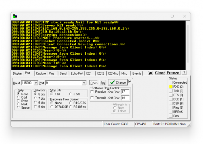
If "Console" is selected as output of Log, then micro USB or USB Type-C port of device will be used for logging. Proper cable must be connected and a teminal should be used to receive Log data. As an example "RealTerm" tool can be used.
Simply select COM port and set baud rate 115200 and data type 8N1 and then click open. Device will send log data.
If "UDP Server" is selected as output of Log, then proper tool must be used to get log data. User must set "UDP Server IP" and "UDP Server Port". Device will send Log to that address. As an example "Package Sender" tool can be used.
Click "File" and then "Settings". Enable "UDP Server" and set the port. Device will send Log data to UDP server.
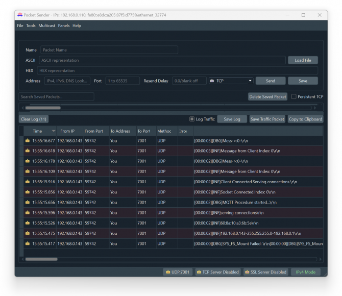
Here is a video example to enable UDP log and receive data via UDP Server software. Video is created with CKL series but applies to all series.
TLM offers auto network discovery feature to gather signal levels, addresses and configuration/connection lists of all TLM devices in same LoRa RF Network which makes installation easier.
Go to "LoRa Status" Menu item.
In "Device Connections over Lora" part:
TLM will show RSSI value - SNR value - Group Address - Device Address of all devices that it is already in communication.
When the "Request LoRa Connections" button clicked, TLM will initiate the discovery process for all devices available for communication in same LoRa Network.
It will show the progress on screen.
Once finished, TLM will show a more detailed list with RSSI value - SNR value - Group Address - Device Address of all devices that it is already in communication as well as Device Ids and Device Details.
In device details part, TLM shows the "Defice Function" of other TLMs in LoRa Network, here are explanations of numbers:
1: “TRANSPARENT - LoRa to TCP Server Gateway”
2: “TRANSPARENT - LoRa to TCP Client Gateway”
3: “TRANSPARENT - LoRa to SERIAL Gateway”
4: “LoRa to Serial Device Gateway with Modbus TCP/RTU Conversion”
5: “LoRa Repeater”
Also if it is 1 (“TRANSPARENT - LoRa to TCP Server Gateway”) or 2 (“TRANSPARENT - LoRa to TCP Client Gateway”), it will show the connected IP list.
NOTE: If there is no TLM device discovered, please try to increase "Radio Power Level" and/or use "SF7" and if possible use at least 1 piece of higher gain antenna that can be mounted on a pole for master TLM device.
LoRa Settings must be same for all device in same LoRa Radio Network
TLM Series LoRa Radio Modems can create a LoRa Based RF network and connect Serial and/or ETH based devices with each other. In this chapter we will communicate between
We will use Modbus simulator as Modbus RTU device and "Modbus Poll" software as Modbus TCP master device in this application
TLM will listen TCP IP connections from the TCP Port set in "Network Settings" Menu. So we will set TLM "Device Function" as "TRANSPARENT - LoRa to TCP Server Gateway" since we donot need and change in protocol and we want it to be transfered over LoRa Radio Network as it is.
The listening TCP port will be "502" as per settings in "Network Settings" Menu.
User may increase "Maximum Number of Clients" if there is more than 1 master in the application.
TLM device and group address will be 1.
Target Group will be same group and it will be 1. Target device will be 2 and we will enter this to remote Modbus RTU device that we will remote read over LoRa Radio Network.
NOTE: Target Device Address must be 65535 (Broadcast address) if there are more than 1 Modbus device to be read in LoRa Radio Network.
User may change "Radio Power Level" if there is too much distance between TLMs and "LoRa Spreading Factor" can be changed to "SF12" for example for higher bandwith (that needs better radio link).
NOTE: If there is no signal coverage, please try to increase "Radio Power Level" and use "SF7" and if possible use at least 1 higher gain antenna that can be mounted on a pole for master TLM device.
LoRa Settings must be same for all device in same LoRa Radio Network.
Those settings will be enough for TLM Modbus TCP side master device.
TLM will get LoRa packages over the air and transfer those packages to local Modbus RTU slave device. So we will set TLM "Device Function" as "LoRa to SERIAL Device Gateway with MODBUS TCP/RTU Conversion" since we need change from Modbus TCP frame to Modbus RTU frame and transfer converted data to local Modbus RTU slave device.
Correct serial port must be enabled since we will connect via Modbus RTU Slave Device such as RS485 if device is connected to RS485 port of TLM. In this example we will use 9600-8N1 for Modbus RTU Slave device connection.
TLM goup address will be 1, same as Master TLM.
TLM device address will be 2, it will be different than the master TLM.
NOTE: Master TLM send packages to target 2 or 65535 (Broadcast address) if there are more than 1 Modbus device to be read in LoRa Radio Network. In both cases slave TLM will get message.
Target Group will be same group and it will be 1. Target device will be 1 since teh master TLM address is 1. That means slave TLM can only send data to master.
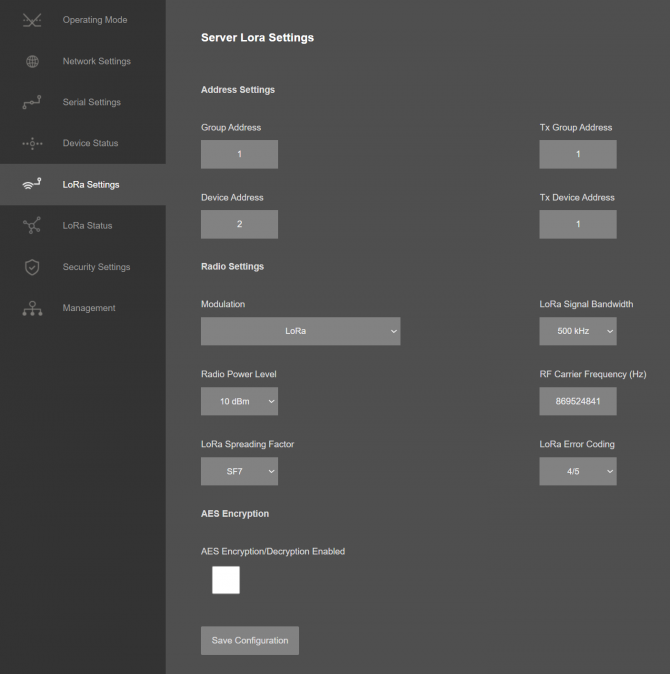
User may change "Radio Power Level" if there is too much distance between TLMs and "LoRa Spreading Factor" can be changed to "SF12" for example for higher bandwith (that needs better radio link).
NOTE: If the re is no signal coverege, please try to increase "Radio Power Level" and use "SF7" and if possible use at least 1 higher gain antenna that can be mounted on a pole for master TLM device.
LoRa Settings must be same for all device in same LoRa Radio Network.
Those settings will be enough for TLM Modbus RTU side slave device.
TLM Series LoRa Radio Modems are now ready for communication between
Modbus RTU slave device address is 5 and we will read 5 register starting from register address 7.
Enter IP and port of Master TLM to Modbus TCP software and set "response timeout" and "delay between polls" according to LoRa network needs.
NOTE: Please remember LoRa is relateivly slow network, so you can set "response timeout" 5000ms and "delay between polls" 1000ms and even more for longer distances.
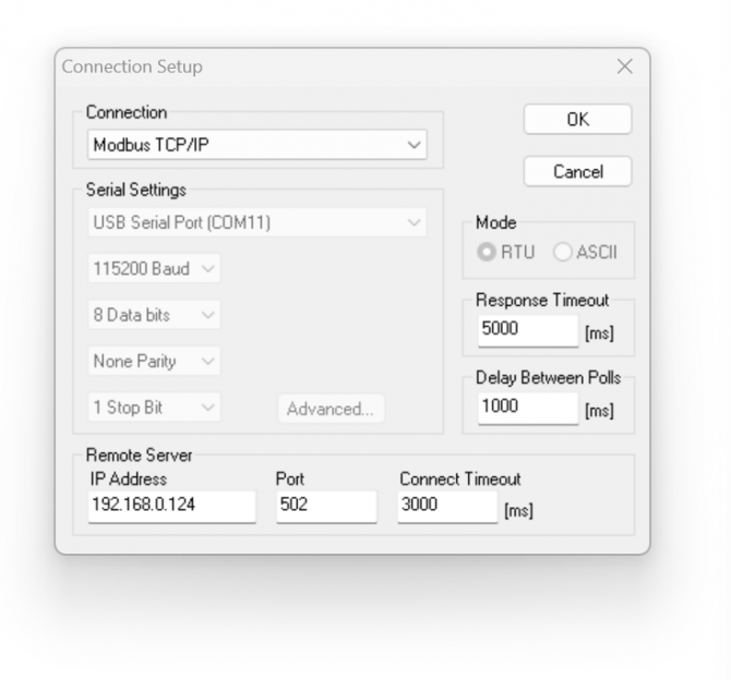
Click "OK" once finished. Software may try to connect, meanwhile please update settings as per your Modbus RTU slave device. In our example Modbus RTU slave device address is 5 and we will read 5 register starting from register address 7.
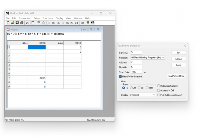
Now the software will read Modbus values. Master TLM side is Modbus TCP, Slave TLM side is Modbus RTU. You can monitor LoRa Status either on Master TLM Modbus TCP side:
Or you can monitor LoRa Status on Slave TLM Modbus RTU side:
TLM Series LoRa Based RF Gateways can link RS232 and/or RS485 serial devices and create a network over RF. For example, with TLM Series LoRa Based RF Gateways users can connect RS232 and/or RS485 Modbus RTU/ASCII devices such as RTUs or PLCs with each other over RF network and create wireless automation.
TLM act as Serial to LoRa RF Gateway when "Device Function" is configured as "Transparent - LoRa to SERIAL Gateway". Serial communication is enabled and settings are done based on field device. LoRa communication configuration must be same along the Lora network. TLM will send LoRa packages to configured Tx Group Address + Tx Device Address combination. User may define 0xFF and 0xFFFF for broadcasting (send LoRa packages to all LoRa devices in LoRa Network). TLM will get LoRa packages from Group Address + Device Address combination and user may keep as default: 0x01 and 0x0001.
HUR Series Modbus TCP Remote I/O Devices Output versions can duplicate input value of Input versions. Outputs can be 5-275V AC-DC, 100mA Digital Optocoupler Output or 5Amperes 250VAC/30VDC Relay Output or 4-20mA Analog Output. Following devices can be used as output device for this application:
HUR158 and HUR258 with 8 Channel 5-275V AC-DC, 100mA Digital Optocoupler Output
HUR168 and HUR268 with 8 Channel Digital 5Amps 250VAC/30VDC Relay Output
Inputs can be 12-275V AC-DC, 60mA Digital Optocoupler Input or 4-20mA Analog Input. Following devices can be used for this application:
As expected, Analog devices can pair with each other and Digital devices can pair with each other.
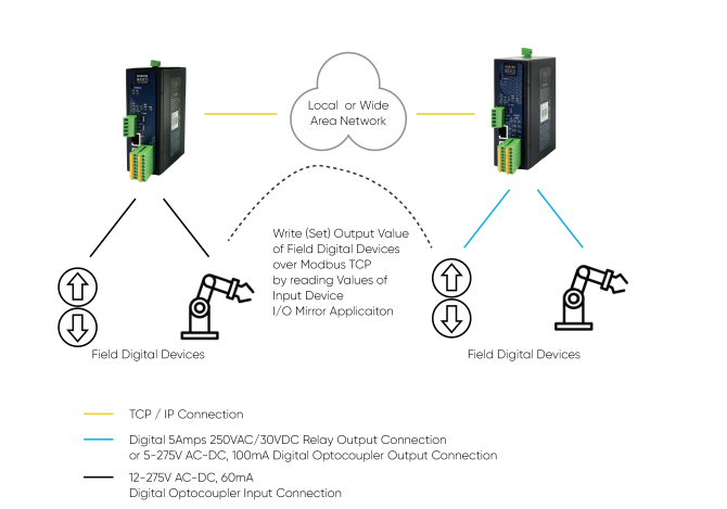
NOTE: I/O Mirror Application can be done between same I/O devices which means Analog devices can pair with each other and Digital devices can pair with each other.
Here is an example video for I/O Mirror application between
The Analog Current value we input from Analog In HUR is set to Analog Out HUR via TLM Series LoRa RF Modems.
Here is the video for configurations:
TLM Series LoRa Based RF Gateways can link TCP/IP devices and create a network over RF. For example, with TLM Series LoRa Based RF Gateways users can connect Modbus TCP devices such as RTUs or PLCs with each other over RF network and create wireless automation.
TLM act as TCP Server to LoRa RF Gateway when "Device Function" is configured as "Transparent - LoRa to TCP Server Gateway". Local ETH client device is connected to TLM Server (User must enter TLM IP and TLM Server Listening port in local device). LoRa communication configuration must be same along the LoRa network. TLM will send LoRa packages to configured Tx Group Address + Tx Device Address combination. User may define 0xFF and 0xFFFF for broadcasting (send LoRa packages to all LoRa devices in LoRa Network). TLM will get LoRa packages from Group Address + Device Address combination and user may keep as default: 0x01 and 0x0001.
TLM act as TCP Client to LoRa RF Gateway when "Device Function" is configured as "Transparent - LoRa to TCP Client Gateway". TLM can automatically connect field devices that are accepting TCP connections on their Modbus TCP port. In that case, field device IP and port must be configured in TLM. LoRa communication configuration must be same along the LoRa network. TLM will send LoRa packages to configured Tx Group Address + Tx Device Address combination. User may define 0x01 and 0x0001 for sending packages back only to TLM connected to Modbus TCP Master device.
HUR Series Modbus TCP Remote I/O Devices can be read via Modbus TCP. TLM series adds RF connectivity to this application.Here is example video to read 2 HUR series Modbus TCP devices over RF Network via Modbus Software..
Here is the physicall application of same example.
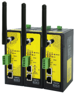
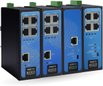
TLM154: 868MHz LoRa RF Modem, 2x 10/100 T(x) ETH ports, 1 x RS232 & 1 x RS485, 5-48V (max. 60V) DC Power Input
TLM254: 868MHz LoRa RF Modem, 2x 10/100 T(x) ETH ports, 1 x RS232 & 1 x RS485, 100 - 240V AC (120 – 370V DC), 50Hz to 60Hz AC Power Input
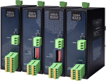
TLM655: 868MHz LoRa RF Modem, 2x 10/100 T(x) ETH ports + 1 x BPL (Broadband Power Line) Link, 1 x RS232 & 1 x RS485, 3 Phase AC Power Input, 110V–240V/50-60Hz
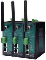
TLM194: 2.4GHz LoRa RF Modem, 2x 10/100 T(x) ETH ports, 1 x RS232 & 1 x RS485, 5-48V (max. 60V) DC Power Input
TLM294: 2.4GHz LoRa RF Modem, 10/100 T(x) ETH ports, 1 x RS232 & 1 x RS485, 100 - 240V AC (120 – 370V DC), 50Hz to 60Hz AC Power Input
TLM695: 2.4GHz LoRa RF Modem, 2x 10/100 T(x) ETH ports + 1 x BPL (Broadband Power Line) Link, 1 x RS232 & 1 x RS485, 3 Phase AC Power Input, 110V–240V/50-60Hz
| Model | Operating Frequency | 5-48V (max.60V) DC Power Input | 100 - 240V AC (120 – 370V DC), 50Hz to 60Hz AC Power Input | 3 Phase AC Power input, 110V–240V/50-60Hz AC Power Input | 2 x 10/100 T(x) ETH Ports | 1 x RS232 and 1 x RS485 Serial Ports | BPL (Broadband Power Line) Link |
| TLM154 | 868MHz | X | X | X | |||
| TLM254 | 868MHz | X | X | X | |||
| TLM655 | 868MHz | X | X | X | X | ||
| TLM194 | 2.4GHz | X | X | X | |||
| TLM294 | 2.4GHz | X | X | X | |||
| TLM695 | 2.4GHz | X | X | X | X |


THIS SITE USES COOKIES
Various types of cookies are used on our website (and on all other digital platforms including mobile applications).
View our new THE INFORMATIVE TEXT ON LPPD AND PRIVACY here.
Google Analytics
Analytical cookies help us to improve our website by collecting and reporting information on its usage.
Google AdWords and Remarketing
We use marketing cookies to help us improve the relevancy of advertising campaigns you receive.
I have read the above articles
 download