- Supports 2 x 10/100Base-T(X) ports
- Supports 1 x RS232 and 1 x RS485 Serial Connection up to 460800 Baud
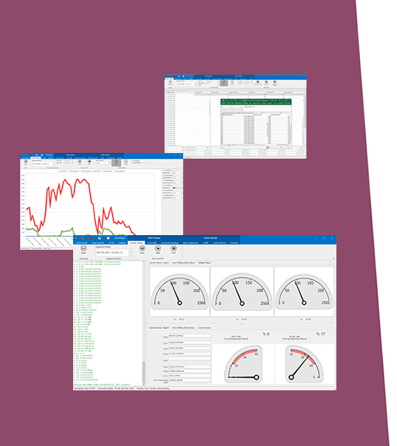
- Embedded web interface for ease of use
- 6 Different Device Functions:
Serial to Ethernet Transparent Gateway Function: Act as transparent gateway between TCP Server and Serial devices or TCP Client and Serial devices
Modbus TCP/RTU Protocol Gateway: Convert Modbus TCP Master devices data to Modbus RTU Protocol or Modbus RTU Master devices data to Modbus TCP Protocol
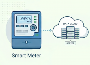
Modbus TCP/RTU Scheduler with MQTT Data Send Function: Reads field Modbus RTU or TCP devices and send their data to MQTT Server
- Up to 32 remote TCP/IP device connection in Modbus TCP/RTU Protocol Gateway Function
- Up to 64 Modbus Commands can be defined in Modbus TCP/RTU Scheduler with MQTT Data Send Function
- MQTT Publisher with different data transfer options in Modbus TCP/RTU Scheduler with MQTT Data Send Function
- Easy to follow Serial and Ethernet data packages on web interface
- Black List and White List based IP Filter in TCP Server Mode
- DHCP Server Capability
- Firmware Upgrade over Web
- 2 firmware storage capability on same device (1 active only)
- Supports 2 x 10/100Base-T(X) ports + 1 x BPL link
- Wide Range 3 phase input, 110V–240V/50-60Hz wide range power input
- Supports up to 30Mbps PHY rate on BPL with Up to 10 hops and 1000 nodes
- Up to 432 sub-carriers from 2 to 28MHz analog bandwidth on BPL
- Support LDPC-C FEC with 128-bit AES core on BPL
- Supports Full/Half-Duplex, auto MDI/MDI-X on each port
- Wide operating temperature range from -40 to 85 °C
- Rugged Metal IP-40 housing design
- DIN-Rail mounting
ETHERNET TECHNOLOGY
Ethernet Standards
IEEE 802.3 for 10Base-T
IEEE 802.3u for 100Base-T(X)
IEEE 802.3x Flow Control
Mac Table
1K MAC address entry
Processing
Store-and-Forward
Memory
448K bits packet buffer memory
BPL (BROADBAND POWERLINE) TECHNOLOGY
PHY Data Rate
Up to 240 MHz
MAC Layer Protocol
CSMA/CA
Modulation Technology
OFDM-432
VLAN
IEEE802.1q/ IEEE802.1p/ IEEE802.3d
NTP TIME SYNCHRONIZATION
NTP is used to synchronize device time. Device checks if NTP time server is available in every 10 seconds after repower. Device synchronizes its time if NTP time is available and stops checking after successfull synchronization.
MODBUS DETAILS - CKL
MQTT Publisher based on Modbus query is available in Device Function:
Modbus TCP/RTU Scheduler with MQTT Data Send
Modbus Protocol
Modbus TCP or RTU Selectable by User
Modbus Devices
Up to 64 Modbus commands can be defined by User
Modbus Address
Independently selectable by User
Modbus Function Code
Read Coil Status (FC=01)
Read Input Status (FC=02)
Read Holding Registers (FC=03)
Read Input Registers (FC=04)
Selectable
Modbus Command Settings
Register Adress
Total Number of Registers
Query Interval
Time Out
Independently Selectable for each command
Modbus RTU Serial Settings
Serial interface RS232 or RS485 Serial data settings and Baud Rate
Independently Selectable for each command
Modbus TCP Settings
TCP/IP and TCP Port Settings
Independently Selectable for each command
MQTT DETAILS - CKL
MQTT Publisher based on Modbus query is available in Device Function:
Modbus TCP/RTU Scheduler with MQTT Data Send
MQTT Connection
Broker IP and Port can be entered
Client ID , User name and Password can be set
Publish Topic and Subscribe Topic can be defined from web interface
Data Send Interval
User can set Data send interval in seconds
Default is 60 seconds and CKL will send Modbus data to MQTT server in that interval
NTP Server
NTP server time will be added to each MQTT message
Data Format
There is 1 predefined format
DATA AS MODBUS FRAME: Send just like the response of Modbus query as hex data
CONNECTORS AND PORTS
Console Port
USB Type C or Micro USB connection for LOG in 115200 baud
10/100T(X) RJ45 Ports
Ethernet Connection on 2 ports
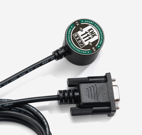
Serial Ports
5 pin wired Terminal Connection
Tx, Rx, GND for RS232
A and B for RS485
Reset Buttons
Reset to Factory Settings Buttons
LED INDICATORS
Power Indicator
Power LED
10/100T(X) Indicators
Activity LEDs:
ETH1, ETH2 and Activity of device itself (Marked as device series name, such as CKL/TLM/HUR/LKM)
System Indicators
Status LED,
Tx and Rx of data LEDs and Server LED
Console Indicators
Tx and Rx of data LEDs
LED INDICATORS - BPL
BPL LEDs
-BPL Activity
-BPL Link
-Master Indication (LED ON: Master, LED OFF: Slave)
POWER - BPL
Power Connection
Powering up device is only done over Terminal pins 1 and 2.
Can be purchased in 2 versions:
1. AC Powered version: Device can be powered up with AC input, this option is available in both PN and PP models. It accepts, 110V–240V/50-60Hz. (Power Input can also be used for data transmission in PN Models.)
2. DC Powered version: Device can be powered up with 9-36V DC power. Data transmission only done through terminal pins 3 and 4. This model can be used if DC power source will be used in the field and available with PP or DC model.
Data Connection
Can be purchased in 3 versions:
1. PP Model: Phase to phase model (Standard Model).
Data transmission is only done through terminal pins 3 and 4. AC Phase to phase connection should be done to data transmission pins for better performance. If phase to phase connection is not available then phase and neutral can still be connected for data transmission over terminal pins 3 and 4.
(Ex: L1-L2, L2-L3, L1-L3 or L1-2-3 to N can be used as data connection)
2. PN Model: Phase to neutral model. That version gets power from terminal pins 1 and 2 from phase and neutral and it can also transmit data from that pins (pins 1 and 2). Remaining (pins 3 and 4) pins usage is optional.
(Ex: Master can be connected to all phases and slaves can be connected to relevant phases)
(Ex: L1-N, L2-N, L3-N or L1-2-3 and N can be used as data connection)
3. DC Model: DC data line model. Uses DC Power Line for data transmission. (Ex: 24V+ and GND as data connection)
PHYSICAL AND ENVIRONMENTAL CHARACTERISTICS - DC POWERED AND BPL MODELS
Enclosure
Metal, IP40
Dimensions
43 x 95 x 124 (w x d x h) mm
Weight
~400gr
Storage Temperature
-65 to 150 °C
Operating Temperature
-40 to 85 °C
Operating Humidity
5% to 95% Non-condensing
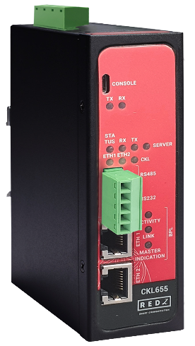
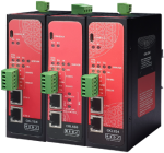
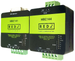
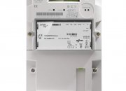
CKL655: Serial to Ethernet Gateway, 2x 10/100 T(x) ETH ports + 1 x BPL (Broadband Power Line) Link, 1 x RS232 & 1 x RS485, 3 Phase AC Power Input, 110V–240V/50-60Hz