Various types of cookies are used on our website (and on all other digital platforms including mobile applications). View our new THE INFORMATIVE TEXT ON LPPD AND PRIVACY here. Google Analytics Analytical cookies help us to improve our website by collecting and reporting information on its usage. Google AdWords ve Remarketing We use marketing cookies to help us improve the relevancy of advertising campaigns you receive.
I have read the above articles
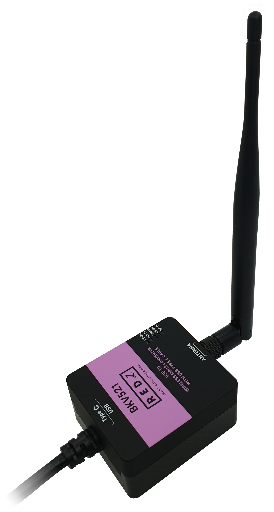
REDZ BKV series are cable-connected communication tools for local applications. All devices has USB Type A or USB Type C connections for local devices such as PCs. It has several options: USB to RS232 Converter or USB to RS485 Converter with built-in isolated 5V Power Output to easily connect field devices such as KMK114, USB 2.0 - 4 Port USB Type A Hub to extend USB connectivity for multiple USB devices like KMK116 series, USB to 2 Port Ethernet switch to connect field devices easier such as STG-LKM-CKL... series, USB to 868MHZ Wireless MBus Converter to get WMBus messages from the local device directly, USB to P1 Companion Protocol Meter Interface Converter to get Electricity meters data directly to local device.
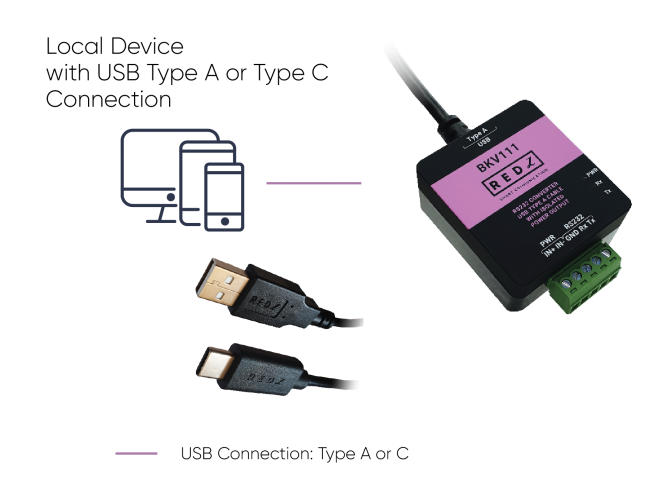
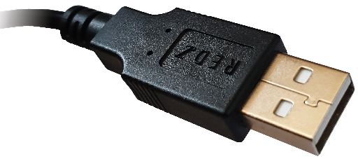
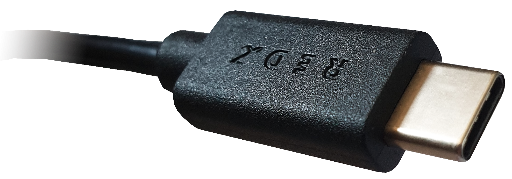
All BKV Series devices have either USB Type A or Type C connection to local device such as PC.
BKV Series USB Communication Tools have very small form factor. Thus, it can be acted as just cable and there is no need for special mounting. Simply connect the USB Type A or Type C cable to PC and latets windows Systems will install driver automatically.
If driver installation fails, user may download driver from following link manually:
BKV USB 2.0 to 2 Port Ethernet Switch Model Drivers
Other Models Drivers can be found on this page:
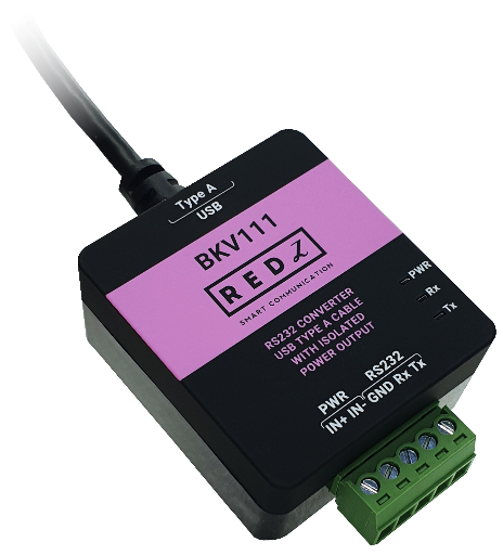
| Pin Number | Description |
| 1 | Tx |
| 2 | Rx |
| 3 | GND |
| 4 |
Isolated Output Power - |
| 5 |
Isolated Output Power + (5VDC) |
| LED | Description |
| PWR | Turns ON if the device is powered properly |
| Rx | Rx and Tx LEDs turn ON during data transfer according to data activity |
| Tx | Rx and Tx LEDs turn ON during data transfer according to data activity |
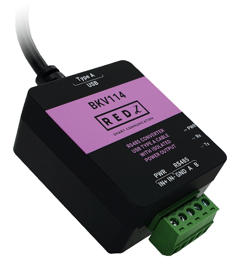
| Pin Number | Description |
| 1 | B |
| 2 | A |
| 3 | GND (Optional) |
| 4 |
Isolated Output Power - |
| 5 |
Isolated Output Power + (5VDC) |
| LED | Description |
| PWR | Turns ON if the device is powered properly |
| Rx | Rx and Tx LEDs turn ON during data transfer according to data activity |
| Tx | Rx and Tx LEDs turn ON during data transfer according to data activity |
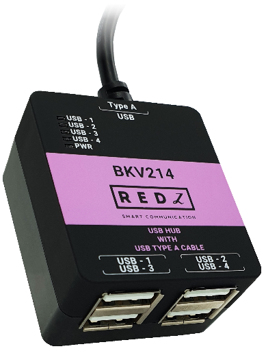
| Port Number | Description |
| 1 | USB Hub - Port 1, USB TYpe A Female |
| 2 | USB Hub - Port 2, USB TYpe A Female |
| 3 | USB Hub - Port 3, USB TYpe A Female |
| 4 |
USB Hub - Port 4, USB TYpe A Female |
| LED | Description |
| PWR | Turns ON if the device is powered properly |
| USB-1 | Turns ON if port 1 is used |
| USB-2 | Turns ON if port 2 is used |
| USB-3 | Turns ON if port 3 is used |
| USB-4 | Turns ON if port 4 is used |
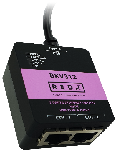
| Port Number | Description |
| 1 | Ethernet Switch Port 1 |
| 2 | Ethernet Switch Port 2 |
| LED | Description |
| PC | Turns ON when device is connected via USB cable and powered up |
| ETH-1 | Turns ON if port 1 is used and there is data activity |
| ETH-2 | Turns ON if port 2 is used and there is data activity |
| FDUPLEX | Ethernet link is Full Duplex when LED is ON and half duplex when LED is OFF |
| SPEED | Ethernet link 100Mbps when LED is ON and 10Mbps when LED is OFF |
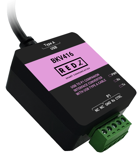
| Pin Number | Description |
| 1 | CTRL (Data Request) |
| 2 | Rx (Data) |
| 3 | GND |
| 4 |
NC: Not Connected |
| 5 |
NC: Not Connected |
User should arrange RJ12 cable needed to connect to meter in desired length.
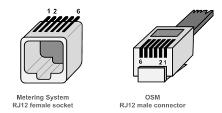
| Pin Number | Description |
| 1 |
+5V Power Supply: NOT USED |
| 2 |
Data Request (CTRL) |
| 3 | Data GND |
| 4 | Not connected (NC) |
| 5 | Data (Rx) |
| 6 | Power GND: NOT USED |
| LED | Description |
| PWR | Turns ON if the device is powered properly |
| Rx | Rx and Tx LEDs turn ON during data transfer according to data activity |
| Tx | Rx and Tx LEDs turn ON during data transfer according to data activity |
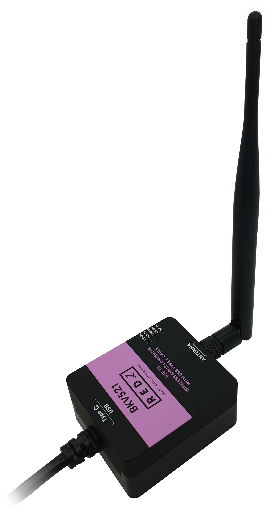
| LED | Description |
| PC-Rx | Turns ON and OFF based on data transmission on USB connection side |
| PC-Tx | Turns ON and OFF based on data transmission on USB connection side |
| Status | Blinks during normal operation |
| RF-Rx | Turns ON and OFF based on data transmission on WMBus side |
| RF-Tx | Turns ON and OFF based on data transmission on WMBus side |
BKV Series USB Communication Tools can be used in different scenarios. Usages are not limited to that examples and user may create their own usage scenario.
BKV Series USB to RS232 Converter with built-in isolated 5V Power Output helps users to easily connect field devices such as KMK111. It has USB Type A and Type C connection options on local field device side (such as PC).
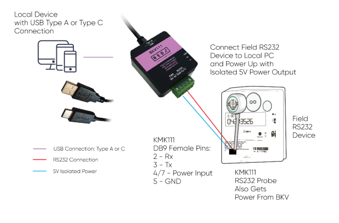
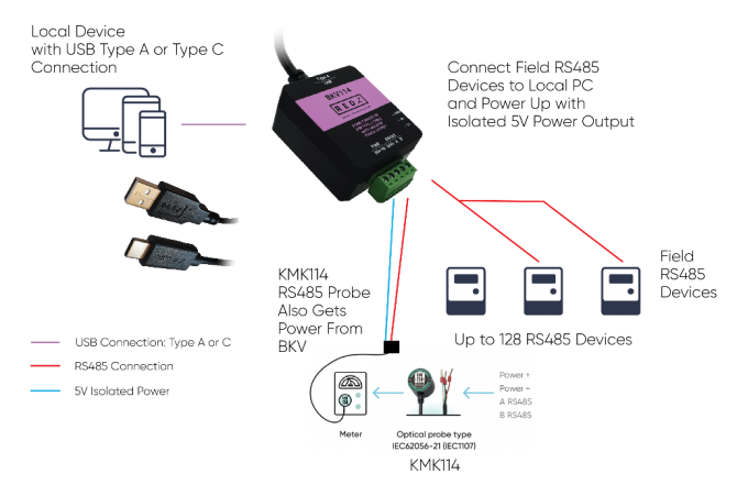
BKV Series USB to RS485 Converter with built-in isolated 5V Power Output helps users to easily connect field devices such as KMK114. It has USB Type A and Type C connection options on local field device side (such as PC).
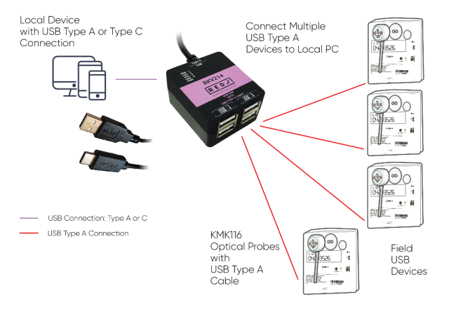
BKV Series USB 2.0 - 4 Port USB Type A Hub helps users to easily extend USB connectivity for multiple USB devices like KMK116 series.
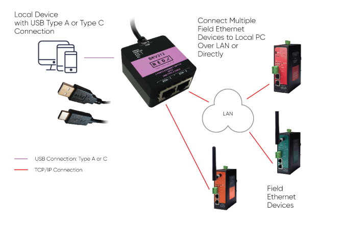
BKV Series USB to 2 Port Ethernet switch helps users to easily connect field devices such as STG-LKM-CKL... series.
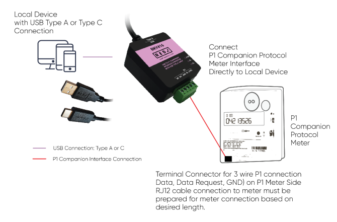
BKV Series USB to P1 Companion Protocol Meter Interface Converter helps users to easily get P1 Electricity meters data directly to local device such as PC.
BKV Series USB to 868MHZ Wireless MBus Converter helps users to easily get WMBus messages from local WMBus devices directly to local PC.
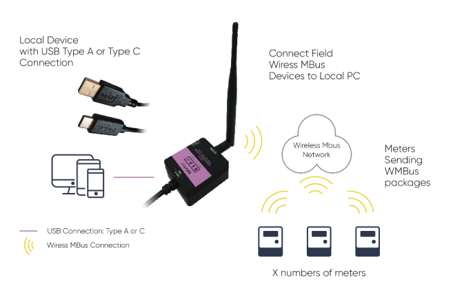
BKV Series USB Communication Tools are easy to operate. Simply connect the USB Type A or Type C cable to PC and latest windows Systems will install driver automatically.

If driver installation fails, user may download driver from following link manually:
BKV USB 2.0 to 2 Port Ethernet Switch Model Drivers
Other Models Drivers can be found on this page:
https://probeformeters.com/en/driver
Here is a video example for reading energy meter with KMK111 RS232 optical probe:
Here is a video example for reading energy meter with KMK114 RS485 optical probe:
Here is a video example for reading 4 energy meters with KMK116 USB optical probes:
Here is a video example for connecting web interface of CKL series over LAN:

| Pin Number | Description |
| 1 |
+5V Power Supply: NOT USED |
| 2 |
Data Request (CTRL) |
| 3 | Data GND |
| 4 | Not connected (NC) |
| 5 | Data (Rx) |
| 6 | Power GND: NOT USED |
Here is a video example for reading an energy meter in P1 Companion Standard:
Supported Link modes are:
| Frequency | Coding | Chiprate | Bitrate | Frame Format | |
| S - Mode | 868.30 MHz | Manchester | 32786 cps | 16384 bps | A |
|
T - Mode (Rx) (Meter to Other) |
868.95 MHz | 3-Out-Of-6 | 10000 cps | 66666 bps | A |
|
T - Mode (Tx) ( Other to Meter) |
868.30 MHz | Manchester | 32768 cps | 16394 bps | A |
|
C - Mode (Rx) (Meter to Other) |
868.95 MHz | NRZ | 100000 cps | 100000 bps | A, B |
|
C - Mode (Tx) ( Other to Meter) |
869.525 MHz | NRZ | 50000 cps | 50000 bps | A, B |
|
C/T - Mode (Rx) (Meter to Other) |
868.95 MHz |
NRZ 3-Out-Of-6 |
10000 cps 10000 cps |
10000 bps 66666 bps |
A, B A |
Supported CI Values are:
| CI-Field | Function / Layer | Up- or Down-link | TPL header - Type | Protocol / Service |
| 53h | Application Reset or Select | Down | Long | Application Reset or Select |
| 5Bh | Command | Down | Long | M-Bus |
| 60h | Command | Down | Long | DLMS |
| 6Ch | Time Sync | Down | Long | Generic |
| 6Dh | Time Sync | Down | Long | Generic |
| 6Eh | Application Error | Up | Short | Generic |
| 6Fh | Application Error | Up | Long | Generic |
| 72h | Response | Up | Long | M-Bus |
| 74h | Alarm | Up | Short | Generic |
| 75h | Alarm | Up | Long | Generic |
| 78h | Response | Up | None | M-Bus |
| 7Ah | Response | Up | Short | M-Bus |
| 7Ch | Response | Up | Long | DLMS |
| 7Dh | Response | Up | Short | DLMS |
| 80h | Pure Transport Layer | Down | Long | None |
| 8Ah | Pure Transport Layer | Up | Short | None |
| 8Bh | Pure Transport Layer | Up | Long | None |
| 8Ch | Extended Link Layer | Up / Down | Short | Lower Layer Service ( 2 Byte ) |
| 8Dh | Extended Link Layer | Up / Down | Long | Lower Layer Service ( 8 Byte ) |
| 8Eh | Extended Link Layer | Up / Down | Long | Lower Layer Service ( 10 Byte ) |
| 8Fh | Extended Link Layer | Up / Down | Long | Lower Layer Service ( 16 Byte ) |
| C3h | Command | Down | Long | Security Information Transport |
| C4h | Response | Up | Short | Security Information Transport |
| C5h | Response | Up | Long | Security Information Transport |
Packet Decryption and Encryption Support List is:
| Mode | Encryption Type | Authentication | Supported |
| 0 | None | None | YES |
| 2 | DES CBC | None | NO |
| 3 | DES CBC | None | NO |
| 5 | AES-128 CBC | None, MIC | YES |
| 7 | AES-128 CBC, dynamic key | CMAC | YES |
| 8 | AES-128 CTR | CMAC | NO |
| 9 | AES-128 GCM | GCM/GMAC | NO |
| 10 | AES-128 CCM | CCM | NO |
| 128 | ELL AES-128 CTR | None, CRC | YES |
| 129 | Custom Modes | None | e.g. AT-WMBUS-NA-1 |
In order to operate Z Terminal software simply click its icon. Then please select COM Port of the device and select device type "BKV WMBus".
Device will communicate in 115200 baud and 8N1 data format.

Click connect when all settings are done and go to "BKV WMBus" tab.
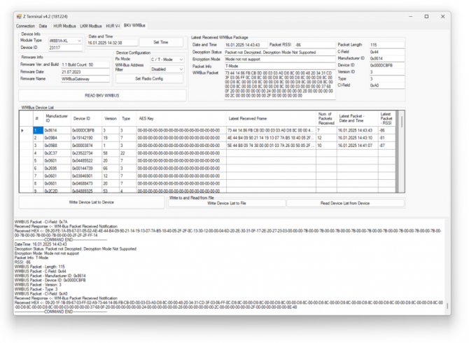
Click "READ BKV WMBUS" button to read


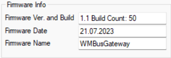


If a WMBus message received over air, the packet will be shown on "Lates Received WMBus Package" part and "WMBus Device List" will be updated:

This part also shows info regarding received packet. And also the terminal will show basic details of received WMBus packet:

In order to send a WMBUs package, go to "Data" tab
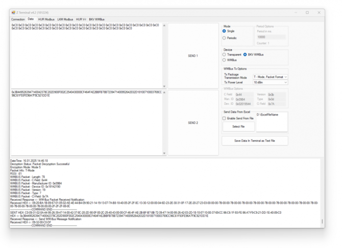


Here is a video example for listening Wireless MBus frames over air with ZTerminal application:
Here is the video for physicall connections of same application:
BKV111: USB to RS232 Converter With USB Type A Cable and 5V Isolated Power Output
BKV114: USB to RS485 Converter With USB Type A Cable and 5V Isolated Power Output
BKV121: USB to RS232 Converter With USB Type C Cable and 5V Isolated Power Output
BKV124: USB to RS485 Converter With USB Type C Cable and 5V Isolated Power Output
BKV214: 4 Port USB 2.0 Type A Hub With USB Type A Cable
BKV224: 4 Port USB 2.0 Type A Hub With USB Type C Cable
BKV312: USB to 2 Port Ethernet Switch With USB Type A Cable
BKV322: USB to 2 Port Ethernet Switch With USB Type C Cable
BKV416: USB to P1 Companion Protocol Meter Interface Converter With USB Type A Cable
BKV426: USB to P1 Companion Protocol Meter Interface Converter With USB Type C Cable
BKV511: USB to 868MHz WMBus (Wireless MBus) Converter With USB Type A Cable
BKV521: USB to 868MHz WMBus (Wireless MBus) Converter With USB Type C Cable
| Model | USB Type A Cable for PC Connection | USB Type C Cable for PC Connection | RS485 Connection and 5V Isolated Power Output | RS232 Connection and 5V Isolated Power Output | 4 Port USB 2.0 Type A Hub | 2 x 10/100 T(x) ETH ports | P1 Companion Meter Interface | 868MHz Wiress MBus (WMBus) |
| BKV111 | X | X | ||||||
| BKV114 | X | X | ||||||
| BKV121 | X | X | ||||||
| BKV124 | X | X | ||||||
| BKV214 | X | X | ||||||
| BKV224 | X | X | ||||||
| BKV312 | X | X | ||||||
| BKV322 | X | X | ||||||
| BKV416 | X | X | ||||||
| BKV426 | X | X | ||||||
| BKV511 | X | X | ||||||
| BKV521 | X | X |
THIS SITE USES COOKIES
Various types of cookies are used on our website (and on all other digital platforms including mobile applications).
View our new THE INFORMATIVE TEXT ON LPPD AND PRIVACY here.
Google Analytics
Analytical cookies help us to improve our website by collecting and reporting information on its usage.
Google AdWords and Remarketing
We use marketing cookies to help us improve the relevancy of advertising campaigns you receive.
I have read the above articles