Various types of cookies are used on our website (and on all other digital platforms including mobile applications). View our new THE INFORMATIVE TEXT ON LPPD AND PRIVACY here. Google Analytics Analytical cookies help us to improve our website by collecting and reporting information on its usage. Google AdWords ve Remarketing We use marketing cookies to help us improve the relevancy of advertising campaigns you receive.
I have read the above articles
 INDEX
INDEX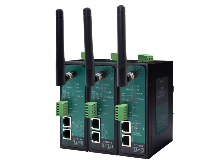
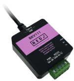
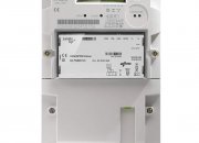
STG Series WMBus Gateways can get Wireless MBus (WMBus) frames over air, Decrypt Up to 64 devices' WMBus packets, parse and map those parsed data to Modbus registers as well as send data to MQTT Server. STG has auto configuration feature to automatically list the received WMBus packages on configuration web interface for easy configuration.
STG has 6 Device Functions:
TCP/IP to WMBus Gateway: Receive WMBus frames and send to TCP IP client device connected to STG. STG can also send WMbus frames from TCP side to WMbus side (generation of frames).
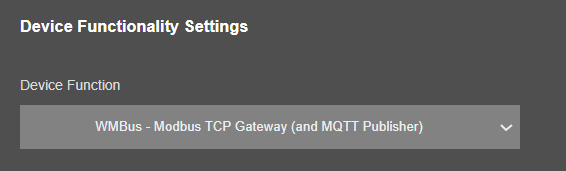
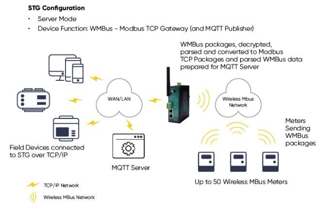
WMBus - Modbus TCP Gateway (and MQTT Publisher): STG can get WMBus frames, decrypt, parse, convert to Modbus TCP (and send to MQTT).
WMBus Decoder/Parser and MQTT Publisher: STG can get WMBus frames, decrypt, parse and send to MQTT ( almost same like function 2 but no Modbus conversion functionality).
Serial to WMBus Gateway: Receive WMBus frames and send to Serial local device connected to STG over RS232 or RS485. STG can also send WMbus frames from serial side to WMbus side (generation of frames).
WMBus - Modbus RTU Gateway (and MQTT Publisher): STG can get WMBus frames, decrypt, parse, convert to Modbus RTU (and send to MQTT).
WMBus Repeater: STG can receive WMBus frames and send them again as WMBus messages to air. This is a repeater function.
In all function modes 1-2-3-4-5-6: STG can decrypt up to 64 devices' frames, for example in Function 6: Repeater function.
Typical applications: Automated Meter reading, Home – Building – Industrial Automation, Wireless Sensors, Telemetry…
STG models with Broadband Power Line (BPL) link can communicate with full transparent TCP/IP standard over Low Voltage power lines and allows easy connection between TCP/IP based terminals without use of extra cables.
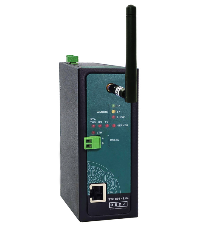
STG Lite Models are cost effective solutions for Wireless MBus Gateway needs. STG- Lite model has hardware and functional differences than normal models.
STG Series WMBus Gateways have the versions with and without BPL (Broadband Power Line) Link.
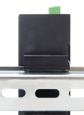
Each device has a Din-Rail kit on rear panel. The Din-Rail kit helps device to fix on the Din-Rail. Slant the switch and mount the metal spring to Din-Rail.
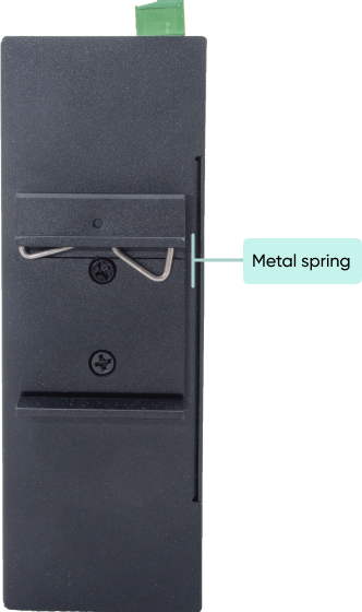
Then Push the switch toward the Din-Rail until you heard a “click” sound.
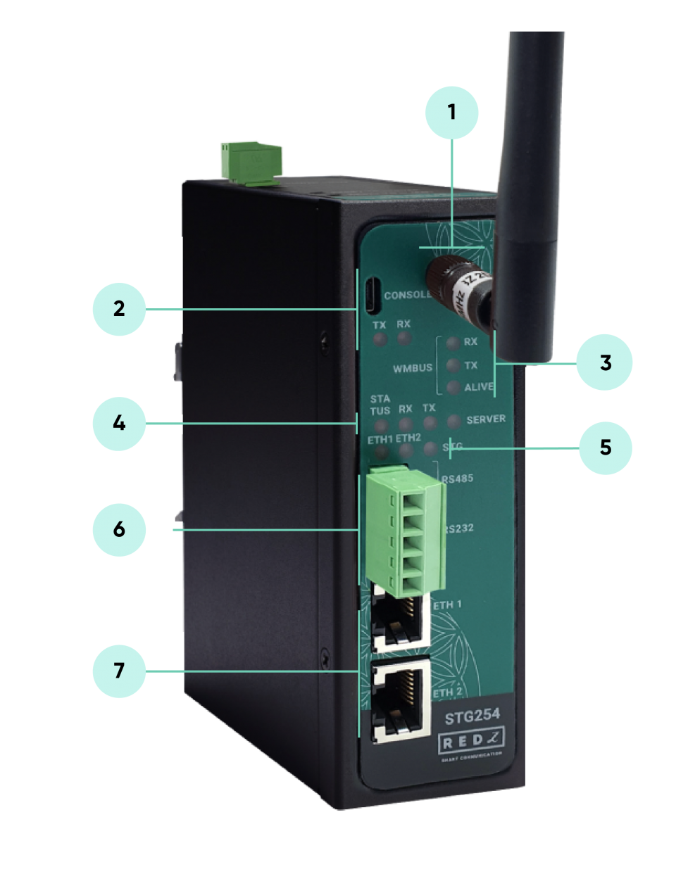
Standard SMA female Antenna interface, 50 ohm.
Micro USB or USB Type-C Console port for LOG in 115200 baud.
Console Tx and Rx Blinks when data transmission occurs.
WMBus Activity LEDs
ALIVE: Blinks during normal operation.
WMBus Tx and Rx Blinks when data transmission occurs.
Device Status LEDs
STATUS: Blinks based on device operation.
- When TCP line used blinks during no connection and keeps ON after TCP connection.
- When Serial line used keeps ON.
Device Tx and Rx Blinks when data transmission occurs.
SERVER: Keeps ON after selecting Server from Server-Client Operating Modes. Keeps OFF if Client operating Mode selected.
ETHERNET Activity LEDs for port 1, 2 and STG device itself. Blinks during ethernet activity.
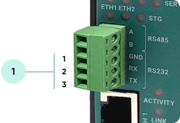
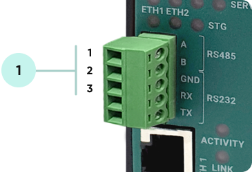
5 pin Terminal Block
RS232: Tx, Rx and GND pins
RS485: A, B and GND pins
Can be activated over web interface and baud rate/data type configurable.
10/100Base-T(X) Ethernet ports
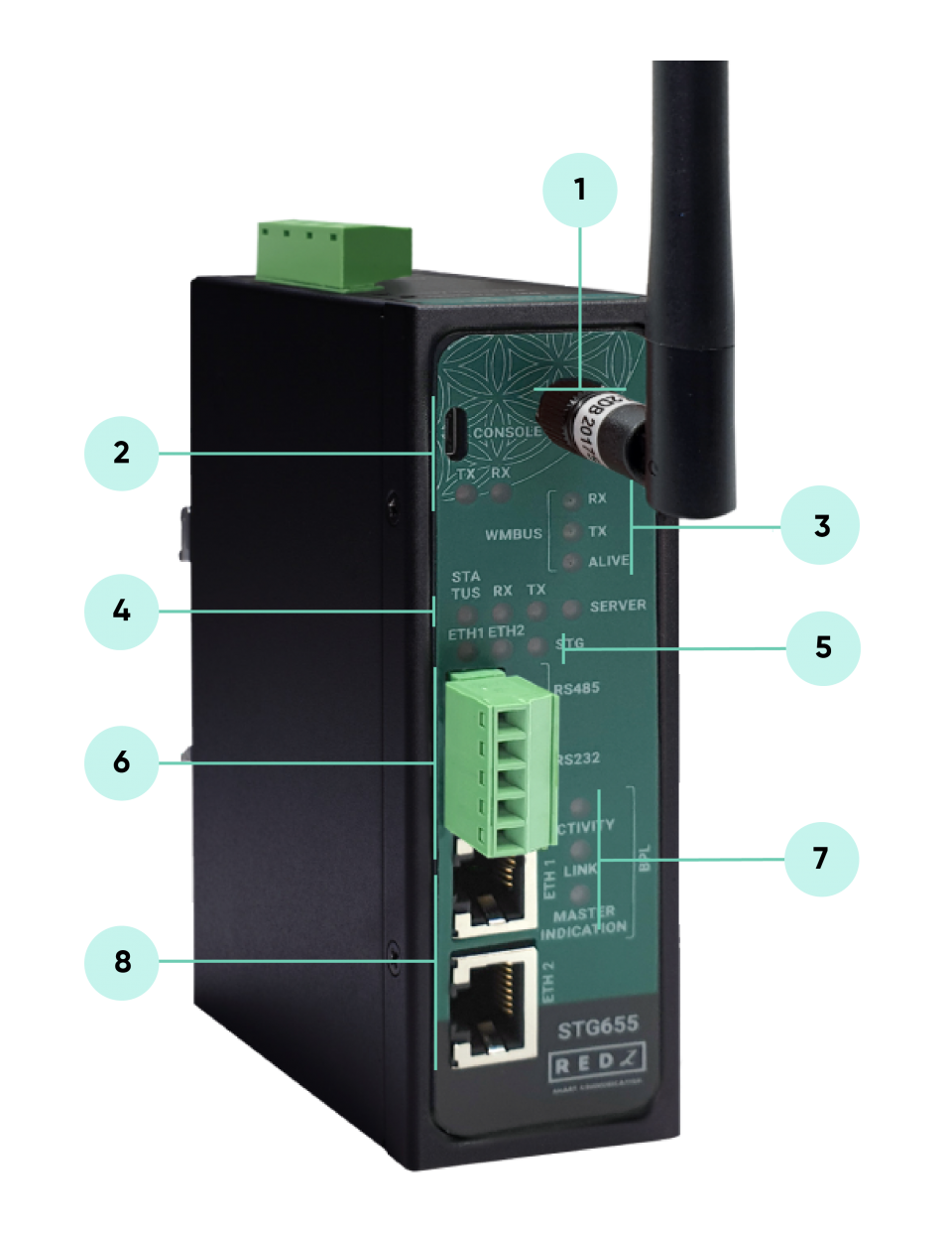
Standard SMA female Antenna interface, 50 ohm.
Micro USB or USB Type-C Console port for LOG in 115200 baud.
Console Tx and Rx Blinks when data transmission occurs.
WMBus Activity LEDs
ALIVE: Blinks during normal operation.
WMBus Tx and Rx Blinks when data transmission occurs.
Device Status LEDs
STATUS: Blinks based on device operation.
- When TCP line used blinks during no connection and keeps ON after TCP connection.
- When Serial line used keeps ON.
Device Tx and Rx Blinks when data transmission occurs.
SERVER: Keeps ON after selecting Server from Server-Client Operating Modes. Keeps OFF if Client operating Mode selected.
ETHERNET Activity LEDs for port 1, 2 and STG device itself. Blinks during ethernet activity.
5 pin Terminal Block for Serial Line
RS232: Tx, Rx and GND pins
RS485: A, B and GND pins
Can be activated over web interface and baud rate/data type configurable
BPL Status LEDs
ACTIVITY: Blinks during BPL Ethernet activity
LINK: LED Turns ON if the link can be established over BPL
MASTER INDICATION: LED Turns ON if the device is configured and powered as “BPL Master” device
10/100Base-T(X) Ethernet ports
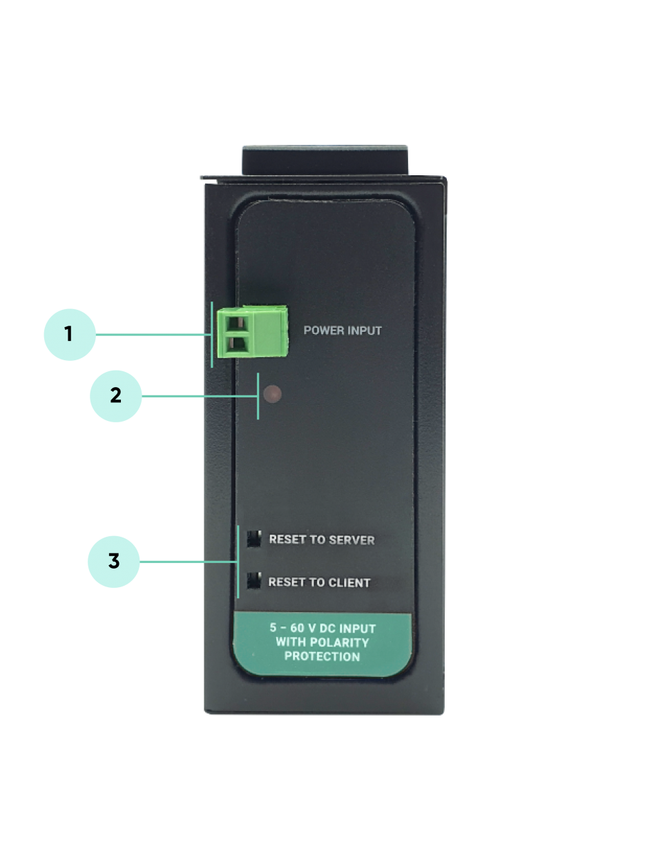
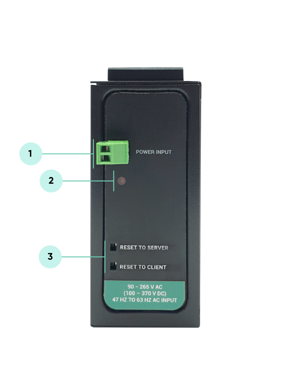
Power Input Options:
AC Power Input 110V–240V/50-60Hz
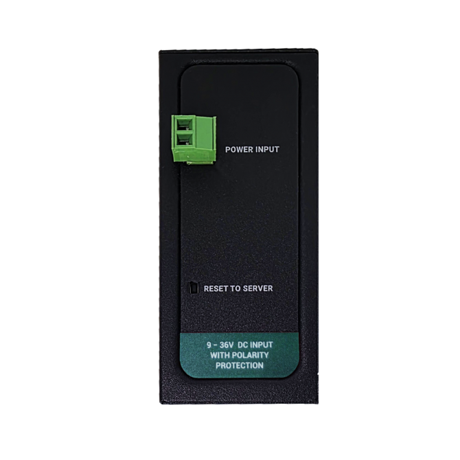
9-36V DC Power Input
Data Connectivity Options:
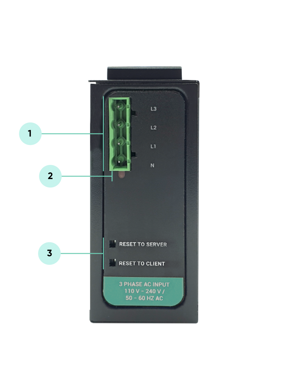
Phase to Phase AC Power Line
Phase to Neutral AC Power Line
DC Power Line

NOTE :
Power Connection
Powering up device is only done over Terminal pins 1 and 2.
Can be purchased in 2 versions:
1. AC Powered version: Device can be powered up with AC input, this option is available in both PN and PP models. It accepts, 110V–240V/50-60Hz. (Power Input can also be used for data transmission in PN Models.)
2. DC Powered version: Device can be powered up with 9-36V DC power. Data transmission only done through terminal pins 3 and 4. This model can be used if DC power source will be used in the field and available with PP or DC model.
Data Connection
Can be purchased in 3 versions:
1. PP Model: Phase to phase model (Standart Model).
Data transmission is only done through terminal pins 3 and 4. AC Phase to phase connection should be done to data transmission pins for better performance. If phase to phase connection is not available then phase and neutral can still be connected for data transmission over terminal pins 3 and 4.
(Ex: L1-L2, L2-L3, L1-L3 or L1-2-3 to N can be used as data connection)
2. PN Model: Phase to neutral model. That version gets power from terminal pins 1 and 2 from phase and neutral and it can also transmit data from that pins (pins 1 and 2). Remaining (pins 3 and 4) pins usage is optional.
(Ex: Master can be connected to all phases and slaves can be connected to relevant phases)
(Ex: L1-N, L2-N, L3-N or L1-2-3 and N can be used as data connection)
3. DC Model: DC data line model. Uses DC Power Line for data transmission. (Ex: 24V+ and GND as data connection)
STG Series WMBus Gateways have standard Ethernet ports. According to the link type, the switches use CAT 3, 4, 5, 5e UTP cables to connect to any other network device (PCs, servers, switches, routers, or hubs).
| Cable | Type | Max. Length | Connector |
| 10BASE-T | Cat. 3, 4, 5 100-ohm | UTP 100 m (328 ft) | RJ-45 |
| 100BASE-TX | Cat. 5 100-ohm UTP | UTP 100 m (328 ft) | RJ-45 |
With 100BASE-TX/10BASE-T cable, pins 1 - 2 are used for transmitting data and pins 3 - 6 are used for receiving data.
| Pin Number | Description |
| 1 | TD+ |
| 2 | TD- |
| 3 | RD+ |
| 4 | Not Used |
| 5 | Not Used |
| 6 | RD- |
| 7 | Not Used |
| 8 | Not Used |
| CAT5 Based System | BPL Link Based System | |
| Media | CAT5 | Power Line |
| Bandwidth | 100Mbps | Up to 30Mbps |
| Re-Wire | Yes | No, Using existing Power Line |
| Span | <100m | <600m |
| Multiple Nodes | N/A | Up to 10 hops/1000 nodes |
| Encryption | Yes, but difficult to configure | Yes, Plug & Play |
| Installment | Difficult | Easy, simply user power line |
| Installment Cost | High | Low |
| Total Cost | High | Low |
NOTE :
Power Connection
Powering up device is only done over Terminal pins 1 and 2.
Can be purchased in 2 versions:
1. AC Powered version: Device can be powered up with AC input, this option is available in both PN and PP models. It accepts, 110V–240V/50-60Hz. (Power Input can also be used for data transmission in PN Models.)
2. DC Powered version: Device can be powered up with 9-36V DC power. Data transmission only done through terminal pins 3 and 4. This model can be used if DC power source will be used in the field and available with PP or DC model.
Data Connection
Can be purchased in 3 versions:
1. PP Model: Phase to phase model (Standart Model).
Data transmission is only done through terminal pins 3 and 4. AC Phase to phase connection should be done to data transmission pins for better performance. If phase to phase connection is not available then phase and neutral can still be connected for data transmission over terminal pins 3 and 4.
(Ex: L1-L2, L2-L3, L1-L3 or L1-2-3 to N can be used as data connection)
2. PN Model: Phase to neutral model. That version gets power from terminal pins 1 and 2 from phase and neutral and it can also transmit data from that pins (pins 1 and 2). Remaining (pins 3 and 4) pins usage is optional.
(Ex: Master can be connected to all phases and slaves can be connected to relevant phases)
(Ex: L1-N, L2-N, L3-N or L1-2-3 and N can be used as data connection)
3. DC Model: DC data line model. Uses DC Power Line for data transmission. (Ex: 24V+ and GND as data connection)
STG Series WMBus Gateways have 1 x RS232 and 1 xRS485 port. Serial line can be connected other serial devices such as RTUs, PLCs, energy meters or any other field device.
| Pin Number | Description |
| 1 | GND |
| 2 | Rx |
| 3 | Tx |
| Pin Number | Description |
| 1 | A |
| 2 | B |
| 3 | GND (Suggested to use) |
NOTE: Lite models have only 2 wire RS485 connection.
Some of the usage scenarios of STG Series WMBus Gateways are described below. Usages are not limited to that examples and user may create their own usage scenarios.
STG Series WMBus Gateways can receive WMBus OMS packages and convert them to Modbus TCP packages. This way WMBus packages of up to 64 meters can directly be collected on a remote or local Data Server or RTU device as Modbus registers and can be used for other applications.

STG Device function is set as "WMBus – Modbus TCP Gateway (and MQTT Publisher)". Manufacturing IDs of field devices can be listed with related Modbus addresses. If needed decryption list can be set and White/Black list can be enabled. Received WMBus OMS messages will be converted to Modbus Registers and field or remote Modbus TCP devices can query that data from related Modbus addresses. The decrypted and parsed data can also be sent to MQTT Server in simultaneoulsy.
NOTE: Lite models supports up to 20 WMBus devices.
STG Series WMBus Gateways can receive WMBus OMS packages and convert them to Modbus RTU packages. This way WMBus packages of up to 64 meters can directly be collected on a remote or local Data Server or RTU device as Modbus registers and can be used for other applications.

STG Device function is set as "WMBus – Modbus RTU Gateway (and MQTT Publisher)". Manufacturing IDs of field devices can be listed with related Modbus addresses. If needed decryption list can be set and White/Black list can be enabled. Received WMBus OMS messages will be converted to Modbus Registers and field or remote Modbus RTU devices can query that data from related Modbus addresses. The decrypted and parsed data can also be sent to MQTT Server in simultaneoulsy (requires LAN and WAN connection).
NOTE: Lite models supports up to 20 WMBus devices.
STG Series WMBus Gateways can receive WMBUS packages, decrypt data and parse. All parsed data can be sent to MQTT server for web based applications in several different formats. This way WMBus packages of up to 64 meters can directly be sent to a local or remote MQTT Server in one of predefined format and data can be analyzed and can be used for monitoring in server applications.

STG Device function is set as "WMBus Decoder/Parser and MQTT Publisher".
NOTE: Lite models supports up to 20 WMBus devices.
STG Series WMBus Gateways can receive WMBus packages and send them to remote or local server over TCP/IP link. This way WMBus packages of unlimited numbers of meters can directly be collected on a remote or local Data Server and that data can be used for other applications.

STG Device function set as "WMBus - TCP/IP Transparent Gateway". Received Wmbus messages can be sent to field or remote TCP/IP devices and up to 64 of them can be decrypted. Same way, the TCP/IP devices can also send WMBus frames to the air ( WMBus network).
NOTE: Message to be sent must be a valid WMBus frame.
Lite models supports up to 20 WMBus devices.
STG Series WMBus Gateways can receive WMBus packages and send them to serial devices over RS232 or RS485. This way WMBus packages of unlimited numbers of meters can directly be collected on a local serial Data Server and that data can be used for other applications.

STG Device function is set as "WMBus - Serial Transparent Gateway". Received Wmbus messages can be sent to RS232 or RS485 serial devices and up to 64 of them can be decrypted. Same way, the serial devices can also send WMBus frames to the air ( WMBus network).
NOTE: Message to be sent must be a valid WMBus frame.
Lite models supports up to 20 WMBus devices.
STG Series WMBus Gateways can receive WMBUS packages and send them back to air to extend WMBus Network range. This way WMBus packages of unlimited numbers of meters can be resend to air again to establish a new WMBus network..
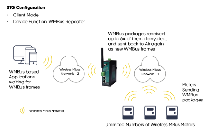
STG Device function is set as "WMBus Repeater". Received WMBus messages resend to air and up to 64 of them can be decrypted.
NOTE: Lite models supports up to 20 WMBus devices.
STG Series WMBus Gateways can be configured over web interface.
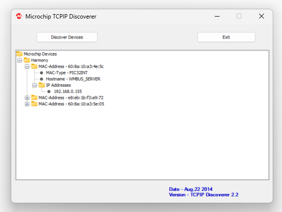
Device will get IP from DHCP client when connected to a network. User can use discovery tool to see IP of the device.

Once the IP of the device is set, user may login the device by simply typing the Ip address of device.
NOTE 1: STG default firmware runs with DHCP off and expects an IP lease. If user needs static IP or prefers DHCP on during start up, it can easily be configured from the the web interface.
NOTE 2: If there is no DHCP server in LAN, REDZ device will get default 192.168.1.1 IP.
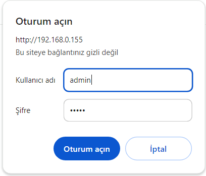
Simply write IP of the device to the http client. Login screen will pop up.
Default user name: admin
Default password: admin
Main screen of device will appear with following information:
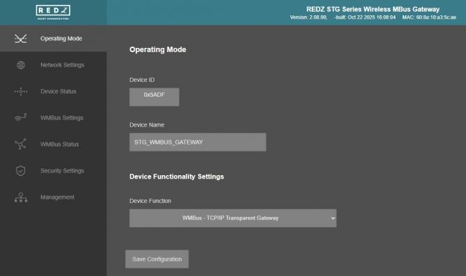
Firmware Info, MAC details and Device Name on top
Menu Items on left
Menu Item details in center
From this menu user may select the operating mode and device function of the device.
NOTE: In all function modes 1-2-3-4-5-6: STG can decrypt up to 64 devices' WMBus frames, for example in Function 6: Repeater function.
Lite models supports up to 20 WMBus devices.
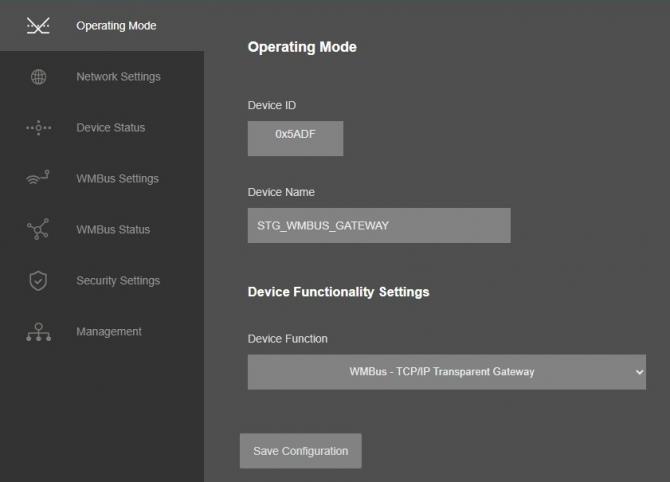
“Device ID” field is the unique Device ID of STG device itself, based on WMBus Module serial number.
“Device Name” field is used to identify device.
“Device Function” field is used to select device behaviour.
EXAMPLES SETTINGS:
STG can act as WMBus to Modbus TCP Gateway and make conversion between WMBus and Modbus TCP protocols and if enabled can also send WMBus data to MQTT Server. STG "Device Function" is set as "WMBus - Modbus TCP Gateway (and MQTT Publisher)".
STG can act as WMBus to Modbus RTU Gateway and make conversion between WMBus and Modbus RTU protocols and if enabled (and connected to LAN/WAN) can also send WMBus data to MQTT Server. STG "Device Function" is set as "WMBus - Modbus RTU Gateway (and MQTT Publisher)".
STG can act as WMBus to MQTT Gateway can WMBus frames, decrypt, parse and send WMBus data to MQTT Server. STG "Device Function" is set as "WMBus Decoder/Parser and MQTT Publisher".
STG can act as WMBus Transparent Gateway and transfer data between WMBus RF Network and field TCP/IP or Serial (RS232 or RS485) devices. STG "Device Function" is set as "WMBus - TCP/IP Transparent Gateway" or "WMBus - Serial Transparent Gateway" based on TCP/IP connectivity need. User can also send WMBus frames to air (WMBus network) in this mode over TCP/IP or Serial lines.
STG can act as WMBus Repeater and simply get WMBus frames and send back to air (WMBus Network) again. This is a repeater function. STG "Device Function" is set as "WMBus Repeater".
If Device Function is set as "WMBus - Modbus TCP Gateway (and MQTT Publisher)" or "WMBus - Modbus RTU Gateway (and MQTT Publisher)", following settings will be shown.
Users may enter Modbus Address that they want to use with field device in this List. They can match the Modbus Address with field WMBus device Manufacturing ID and they can enable the entry they use.
Similar screen will be available if "WMBus Decoder/Parser and MQTT Publisher" selected as "Device Function" without the Modbus Addresses.
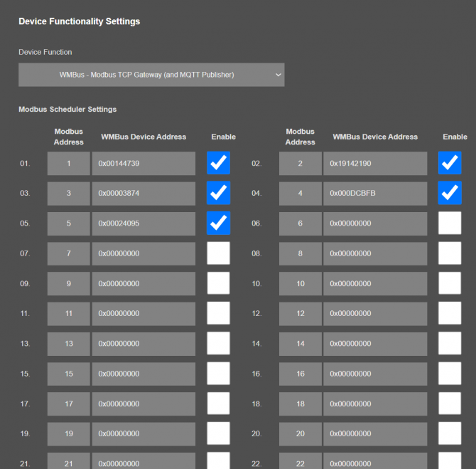
“Modbus Address” Modbus Address to be used to Access Modbus registers for field WMBus Device
“WMBus Device Address” Manufacturing ID of field WMBus Device that matched with Modbus Address
“Enable” Option to enable or disable the entry
NOTE: STG Series WMBus Gateways have built in mechanism to get WMBus frames and Auto Configure which is described in "WMBus Settings" menu. This list can be auto filled by Auto Configuration mechanism, thus user do not have to enter manually.
STG has capability to decrypt and convert WMBus data to Modbus protocol for up to 64 devices.
STG Lite Models have capability to decrypt and convert WMBus data to Modbus protocol for up to 20 devices.
D16 Models support up to 20 devices for Modbus conversion and up to 16 devices for decryption.
Once the setting has been changed, “Save Configuration” button will be enabled.

After clicking button system will tell if the settings applied successfully or not.
NOTE 1: Settings will be applied once the device is rebooted from web interface or repowered manually.
NOTE 2: If STG will be used to generate WMBus packages and TCP/IP connection will be used for that, there are 2 options:
1. "Device Function" is set to "WMBus - TCP/IP Transparent Gateway".
2. "Device Function" is set to "WMBus - Serial Transparent Gateway".
STG will act as WMBus to TCP/IP - Serial Transparent Gateway and can send data from WMBus to TCP/IP - Serial or send TCP/IP - Serial data to WMBus RF Network (generate WMBus frames).
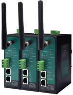
STG has 2 versions as hardware as well:
STG has capability to decrypt and convert WMBus data to Modbus protocol for up to 64 devices and Lite Models up to 20 devices. Those versions can receive WMBus frame from TCP/IP as it is and send to WMBus RF Network.
There is also a version with up to 20 devices for Modbus conversion and up to 16 devices for decryption. If that version is used, HCI protocol must be used to generate WMBus frames.
HCI protocol:
SOF (Start of Frame): 0xA5
Message Header Field: 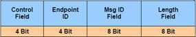
Control Field: User may use 0x0 for this part to ignore CRC16 attachment at end
Endpoint ID: It is 0x2
Message ID Field: It is 0x01 for sending data
Length Field: It is the payload length which means data size of framed WMBus package
Example WMBus Message:
| Frame in Hex |
| 0E 06 23 12 67 45 23 01 01 01 80 54 65 73 74 |
Example encapsulated WMBus Message with HCI protocol:
| Frame in Hex |
| A5 02 01 0E 06 23 12 67 45 23 01 01 01 80 54 65 73 74 |
Please contact our company if you need full implementation of protocol including CRC16 calculation.
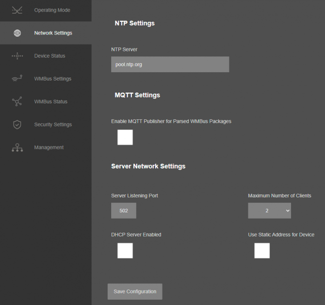
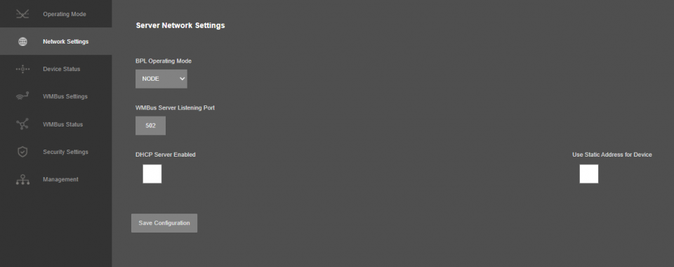
From this menu user may change the network settings of the device.
NOTE: NTP is used to syncronize device time after a manual or system triggered restart and it only takes place if NTP time is available and device time difference from NTP time is + or - 24 Hours.
System will also make adjustments if the device time is lagging in minute within 60 minutes time window.
Also following options are available when "Device Function" is set to “WMBus - Modbus TCP Gateway (and MQTT Publisher)”, "WMBus Decoder/Parser and MQTT Publisher", or "WMBus - Modbus RTU Gateway (and MQTT Publisher)".
Also following options are available when "Device Function" is set to “WMBus - TCP/IP Transparent Gateway”.
"NTP Server": NTP Server address that used in MQTT data transmission.
"Enable MQTT Publisher for Parsed WMBus Packages": Click to enable MQTT Publisher. STG will send data read from WMBus meters for enabled devices (there are up to 64 available for standard models and up to 20 for other models) to MQTT Server. Data can only be sent if the WMBus frame can be decrypted and parsed.
This option is availble when "Device Function" is set to “WMBus - Modbus TCP Gateway (and MQTT Publisher)”, "WMBus Decoder/Parser and MQTT Publisher", or "WMBus - Modbus RTU Gateway (and MQTT Publisher)".
If "Enable MQTT Publisher for Parsed WMBus Packages" is checked, following settings will be shown.
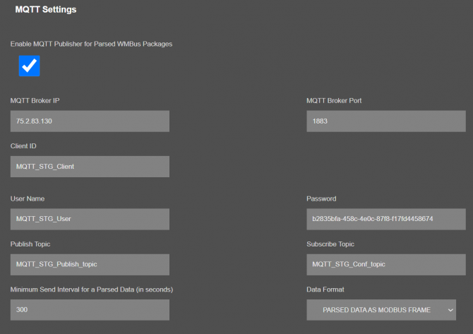
"MQTT Broker IP": TCP IP of the MQTT Server. User must enter IP value
Ex: 75.2.83.130 is for "https://tago.io/" web address
"MQTT Broker Port": TCP Port of the MQTT Server.
Ex: 1883 is for "https://tago.io/" web address
"Client ID": MQTT Publisher client ID. Default is MQTT_STG_Client.
Maximum length for this field is 32.
"User Name": MQTT Publisher user name. This must be entered based on MQTT server settings.
Maximum length for this field is 64.
"Password": MQTT Publisher password. This must be entered based on MQTT server settings.
Maximum length for this field is 48.
"Publish Topic": MQTT Publisher topic value. Default is MQTT_STG_Publish_topic.
Maximum length for this field is 32.
"Subscribe Topic": MQTT Publisher subscribe topic value. Default is MQTT_STG_Subscribe_topic.
Maximum length for this field is 32.
"Minimum Send Interval for a Parsed Data (in seconds)": Minimum value to send meter data to MQTT Server. This time is the minimum time to send data to server, if WMBus meter sends frames in longer periods then it will be basis of the sending interval.
"Data Format": Options for how data is shared by STG with MQTT server. There are 2 options:
RAW WMBUS DECRYPTED DATA
PARSED DATA AS OBJECTS
PARSED DATA AS MODBUS FRAME
When selected as "Raw WMBus Decrypted Data", STG will share WMBus frame as it is but decrypted as follows as an example:
MQTT message shows STG device name, device id, NTP time and data itself
Data has values of WMBus Device Id, Manufacturer Id, Device Version, Device Type, RSSI Value of recevied signal, Access Number value and Decrypted frame Data Block.
When selected as "Parsed Data As Objects", STG will share WMBus data as parsed objects as follows as an example:
MQTT message shows STG device name, device id, NTP time and data itself
Data has values of WMBus Device Id, Manufacturer Id, Device Version, Device Type, RSSI Value of recevied signal, Access Number value.
Parsed Data is shared in blocks and Data Count value shows how many blocks are there.
In this example there is 1 block
{\"S\":\"0\",\"F\":\"1\",\"T\":\"3\",\"V\":\"1751900.0\"}
Here are explanations:
S: Storage Number (of data from meter)
F: Function Field (of data from meter)
T: Data Type (STG uses this value to identify type of Data)
V: Data Value (can be float or UINT - 4 byte data, matched with Data Type)
NOTE: Parsed data shared as data blocks. This is valid for both Modbus Frames and web page visualization. Each data block has following values:
- Data Type specified by STG
- Data Value (can be a float or long value)
- Function, available values are:
INSTANTANEOUS, MAXIMUM, MINIMUM or ERROR STATE
- Data Storage Number as an integer
details are explained in "Chapter 11: WMBus Data Parsing Format".
When selected as "Parsed Data As Modbus Frame", STG will share WMBus data as Modbus like frame as follows as an example:
MQTT message shows STG device name, device id, NTP time and data itself
Data has values of WMBus Device Id, Manufacturer Id, Device Version, Device Type, RSSI Value of recevied signal, Access Number value.
Parsed Data is shared in Modbus like frame, in this example as follows.
1A00144739269500420037000100000001000349D5DAE0002DFFCD
1A: 1 byte frame length, which is 1Ah and which is 26 in decimal and WMBus data shared as blocks
00144739: 4 bytes of WMBus device id
2695: 2 bytes of WMBus device manufacturer id
0042: 2 bytes of WMBus device version
0037: 2 bytes of WMBus device type
0001: 1 byte of Data count value. Data shared in blocks and this value shows how many blocks are there
00000001000349D5DAE0: Each data blocks has following values in 6 registers and 12 bytes
Storage Number (of data from meter) - 2 bytes
Function Field (of data from meter) - 2 bytes
Data Type (STG uses this value to identify type of Data that is shown in previous example) - 2 bytes, Data Type is Volume in this example
Data Value (float data based on Data Type in this example) - 4 bytes, 1751900.0 in this example
002D: 1 byte of Access Number value as unsigned integer. 45 in this example.
FFCD: 1 byte of RSSI value as signed integer. -51 in this example.
NOTE: Parsed data shared as data blocks. This is valid for both Modbus Frames and web page visualization. Each data block has following values:
- Data Type specified by STG
- Data Value (can be a float or long value)
- Function, available values are:
INSTANTANEOUS, MAXIMUM, MINIMUM or ERROR STATE
- Data Storage Number as an integer
details are explained in "Chapter 11: WMBus Data Parsing Format".
There is also 4 registers at the end of each frame (service registers) to show Access Number, RSSI value, Status value of frame and Decryption Status.
Following parameters are available when "Device Function" is set to “WMBus - TCP/IP Transparent Gateway”
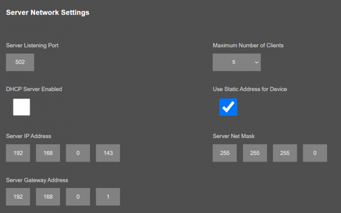
"Listening Port": TCP Port that STG uses for incoming connections. Remote devices can use STG IP and this port to connect to STG for Modbus TCP query.
"Maximum Number of Clients": Maximum numbers of incoming connections accepted. STG can accept up to 10 simultaneous connection and all devices can query Modbus TCP.
"Use Static Address for Device": Set a static TCP IP for STG from this part. Enable and enter network settings and STGwill be available to connect from this static IP locally or remotely (gateway must be set properly for remote WAN connection).
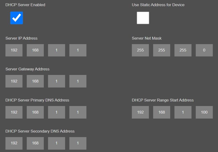
Following parameters available if “DHCP Server” setting is enabled. This is used if DHCP server is needed in network. STG can distribute IP to field devices connected to it in this way.
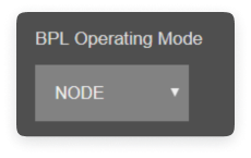
Also if the device has Broadband Power Line (BPL) option:
User can select operating mode of BPL either MASTER or NODE.
NOTE: Standard firmware of REDZ BPL supports up to 10 hops and 1000 nodes. Only 1 device can be MASTER in same network.
Once the setting has been changed, “Save Configuration” button will be enabled.
After clicking button system will tell if the settings applied successfully or not.
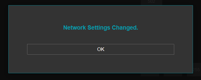
NOTE: Settings will be applied once the device is rebooted from web interface or repowered manually.
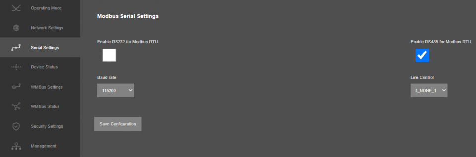
This menu is available only when "Device Function" is set to “WMBus - Serial Transparent Gateway” or "WMBus - Modbus RTU Gateway (and MQTT Publisher)".
From this menu user may activate RS232 or RS485 connection.
NOTE: Lite models only support RS485 serial connection.
Here are menu options:
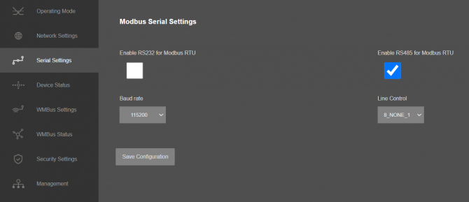
“RS232” Enable RS232 serial line for Modbus RTU or Serial line transparent communication.
“Rs485” Enable RS485 serial line for Modbus RTU or Serial line transparent communication.
"Baud rate": Serial communication baud rate selection.
"Line Control": Serial communication data type selection in form of Data bits-Parity-Stop bits. Available options are:
8_NONE_1
9_NONE_1
8_EVEN_1
8_EVEN_2
8_ODD_1
8_ODD_2
8_NONE_2
9_NONE_2
Once the setting has been changed, “Save Configuration” button will be enabled.
After clicking button system will tell if the settings applied successfully or not.
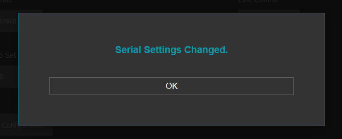
NOTE 1: Settings will be applied once the device is rebooted from web interface or repowered manually.
NOTE 2: If STG will be used to generate WMBus packages and TCP/IP connection will be used for that, there are 2 options:
1. "Device Function" is set to "WMBus - TCP/IP Transparent Gateway".
2. "Device Function" is set to "WMBus - Serial Transparent Gateway".
STG will act as WMBus to TCP/IP - Serial Transparent Gateway and can send data from WMBus to TCP/IP - Serial or send TCP/IP - Serial data to WMBus RF Network (generate WMBus frames).
STG has 2 versions as hardware as well:
STG has capability to decrypt and convert WMBus data to Modbus protocol for up to 64 devices and Lite Models up to 20 devices. Those versions can receive WMBus frame from one of serial line (RS232 or RS485) as it is and send to WMBus RF Network.
There is also a version with up to 20 devices for Modbus conversion and up to 16 devices for decryption. If that version is used, HCI protocol must be used to generate WMBus frames.
HCI protocol:
SOF (Start of Frame): 0xA5
Message Header Field:
Control Field: User may use 0x0 for this part to ignore CRC16 attachment at end
Endpoint ID: It is 0x2
Message ID Field: It is 0x01 for sending data
Length Field: It is the payload length which means data size of framed WMBus package
Example WMBus Message:
| Frame in Hex |
| 0E 06 23 12 67 45 23 01 01 01 80 54 65 73 74 |
Example encapsulated WMBus Message with HCI protocol:
| Frame in Hex |
| A5 02 01 0E 06 23 12 67 45 23 01 01 01 80 54 65 73 74 |
Please contact our company if you need full implementation of protocol including CRC16 calculation.
From this menu user may monitor device status and statistics based on operating mode of device. The page also helps users to check device health.
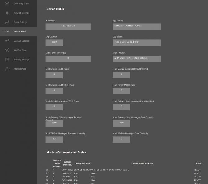
"IP Address": TCP/IP address of STG itself.
"App Status": It shows current status of STG application. "SERVING CONNECTIONS" means device is ready for normal operation.
"Log Status": It is only available when "Log" is enabled from "Management" menu and shows current status of STG logging. "LOG_STATE_TRYWRITELOG" means normal operation.
"Log Counter": It is only available when "Log" is enabled from "Management" menu and shows how many log lines has been transfered till now.
"MQTT Sent Messages": It is only available when "MQTT" is enabled from "Network Settings" menu and shows how many MQTT messages has been transfered till now.
"MQTT Status": It is only available when "MQTT" is enabled from "Network Settings" menu and shows current status of STG MQTT Publisher. "APP_MQTT_STATE_SUBSCRIBED" means MQTT publisher is ready for normal operation.
"N. of Module UART Errors": Number of module uart errors.
“N. of Module Incorrect Chars Received” Number of incorrect packages length that does not fit Protocol Data Unit that device uses.
“N. of Module UART CRC Errors” Number of CRC errors based on Protocol Data Unit that device uses.
"N. of WMBus Messages Received Correctly": Number of WMBus packages received successfully over the WMBus Network.
"N. of WMBus Messages Sent Correctly": Number of WMBus packages sent to WMBus Network successfully.
Following status variables also availbale when "Device Function" is set to “WMBus - TCP/IP Transparent Gateway” or "WMBus - Modbus TCP Gateway (and MQTT Publisher)".
"N. of TCP Disconnections": Number of TCP disconnections from STG.
"N. of TCP Output Full Errors": Number of TCP output full errors during trying to send data to TCP side. Device will enter "Reboot State" if this number is above 5.
"N. of Gateway Side Messages Received Correctly": Number of data packages received from TCP side.
"N. of Gateway Side Messages Sent Correctly": Number of data packages sent to TCP side based.
Following status variables also availbale when "Device Function" is set to “WMBus - Serial Transparent Gateway”.
"N. of Serial UART Errors": Number of serial uart errors.
Following status variables also availbale when "Device Function" is set to "WMBus - Modbus RTU Gateway (and MQTT Publisher)".
"N. of Serial UART Errors": Number of serial uart errors.
“N. of Serial Side Modbus CRC Errors” Number of CRC errors based on Modbus Protocol Data Unit.
“N. of Gateway Side Incorrect Chars Received” Number of incorrect packages length that does not fit Modbus Protocol Data Unit.
In "Modbus Communication Status" part (Available when "Device Function" is Set to "WMBus - Modbus TCP Gateway (and MQTT Publisher)" or "WMBus - Modbus RTU Gateway (and MQTT Publisher)"):
Device will show 64 lines in standard models (20 lines for other models) in this part to show modbus communciation status of each WMBus device available for decryption and parsing.
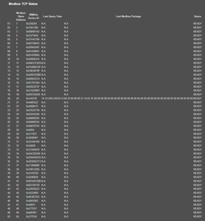
"Modbus Slave Address": Is the Modbus Slave address for the device in entry.
"WMBus Device ID": Is the device id of WMBus meter that is queried.
"Last Query Date": Is the last time the modbus query is executed.
"Last Modbus Package": Is the last modbus frame sent for the WMBus meter in entry.
"Status": Is the status for communication.
In "Connections" part (Available when "Device Function" is Set to "WMBus - TCP/IP Transparent Gateway"):
Device can show up to 10 lines in this part based on "Maximum Number of Clients" setting under "Network Settings" Menu.
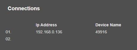
"Ip Address": Is the TCP IP address of client connected to STG.
"Incoming Port": Is the TCP Port of socket used by client connected to STG.
After clicking “Refresh Status” button, system will reload data only and will not reload page. Button will be disabled during reload for an instance. If timeout occurs during the reload, the button will be enabled again with warning of timeout. In normal operation reload of status data will be done immediately.
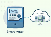
The Wireless MBus protocol stack implemented on STG is compliant the European standard 13757 part 4: "Communication systems for meters and remote reading of meters". It describes the wireless communication of water, heat, electricity and gas meters with data concentrators.
From this menu user may change following WMBus RF parameters:
NOTE: STG Series WMBus Gateways have built in mechanism to get WMBus frames and Auto Configure. AES Decryption, Modbus Adress mapping and Black list items can be auto filled by Auto Configuration mechanism, thus user do not have to enter manually each item besides AES Key.
STG has capability to decrypt and convert WMBus data to Modbus protocol for up to 64 devices.
STG Lite Models have capability to decrypt and convert WMBus data to Modbus protocol for up to 20 devices.
D16 Models support up to 20 devices for Modbus conversion and up to 16 devices for decryption.
Supported Link modes are:
| Frequency | Coding | Chiprate | Bitrate | Frame Format | |
| S - Mode | 868.30 MHz | Manchester | 32786 cps | 16384 bps | A |
|
T - Mode (Rx) (Meter to Other) |
868.95 MHz | 3-Out-Of-6 | 10000 cps | 66666 bps | A |
|
T - Mode (Tx) ( Other to Meter) |
868.30 MHz | Manchester | 32768 cps | 16394 bps | A |
|
C - Mode (Rx) (Meter to Other) |
868.95 MHz | NRZ | 100000 cps | 100000 bps | A, B |
|
C - Mode (Tx) ( Other to Meter) |
869.525 MHz | NRZ | 50000 cps | 50000 bps | A, B |
|
C/T - Mode (Rx) (Meter to Other) |
868.95 MHz |
NRZ 3-Out-Of-6 |
10000 cps 10000 cps |
10000 bps 66666 bps |
A, B A |
Supported CI Values are:
| CI-Field | Function / Layer | Up- or Down-link | TPL header - Type | Protocol / Service |
| 53h | Application Reset or Select | Down | Long | Application Reset or Select |
| 5Bh | Command | Down | Long | M-Bus |
| 60h | Command | Down | Long | DLMS |
| 6Ch | Time Sync | Down | Long | Generic |
| 6Dh | Time Sync | Down | Long | Generic |
| 6Eh | Application Error | Up | Short | Generic |
| 6Fh | Application Error | Up | Long | Generic |
| 72h | Response | Up | Long | M-Bus |
| 74h | Alarm | Up | Short | Generic |
| 75h | Alarm | Up | Long | Generic |
| 78h | Response | Up | None | M-Bus |
| 7Ah | Response | Up | Short | M-Bus |
| 7Ch | Response | Up | Long | DLMS |
| 7Dh | Response | Up | Short | DLMS |
| 80h | Pure Transport Layer | Down | Long | None |
| 8Ah | Pure Transport Layer | Up | Short | None |
| 8Bh | Pure Transport Layer | Up | Long | None |
| 8Ch | Extended Link Layer | Up / Down | Short | Lower Layer Service ( 2 Byte ) |
| 8Dh | Extended Link Layer | Up / Down | Long | Lower Layer Service ( 8 Byte ) |
| 8Eh | Extended Link Layer | Up / Down | Long | Lower Layer Service ( 10 Byte ) |
| 8Fh | Extended Link Layer | Up / Down | Long | Lower Layer Service ( 16 Byte ) |
| C3h | Command | Down | Long | Security Information Transport |
| C4h | Response | Up | Short | Security Information Transport |
| C5h | Response | Up | Long | Security Information Transport |
Packet Decryption and Encryption Support List is:
| Mode | Encryption Type | Authentication | Supported |
| 0 | None | None | YES |
| 2 | DES CBC | None | NO |
| 3 | DES CBC | None | NO |
| 5 | AES-128 CBC | None, MIC | YES |
| 7 | AES-128 CBC, dynamic key | CMAC | YES |
| 8 | AES-128 CTR | CMAC | NO |
| 9 | AES-128 GCM | GCM/GMAC | NO |
| 10 | AES-128 CCM | CCM | NO |
| 128 | ELL AES-128 CTR | None, CRC | YES |
| 129 | Custom Modes | None | e.g. AT-WMBUS-NA-1 |
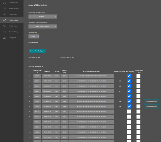
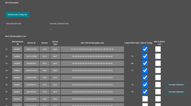
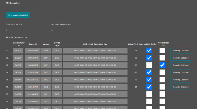
Here is an example for "AES Decryption" part: After clicking of "Refrefsh Auto Config List", STG will fill WMBus device address, Manufacturer ID, Device version and Device Type based on received frames.
In this example entries 1 to 5 are from previous configuration (already saved in configuration) and entries 6 & 7 are new frames and marked with "Recently Dedected" sign. User can mark those devices as "Add to Config" ( and enter AES Key) or "Add to Black List".
If "Add to Config" checked, user must enter AES Key (if Key is used). After clicking "Save Configuration", STG will save this entry and add that device to "Modbus Scheduler Settings" under "Operating Mode" menu.
If "Add to Black List" checked, after clicking "Save Configuration", STG will save this device id under "Black List Table" (and enables list by checking "Black List Enabled" checkbox, if not enabled already) under "Security Settings" menu. This entry also will be freed up from decryption list to be used for new coming frames.
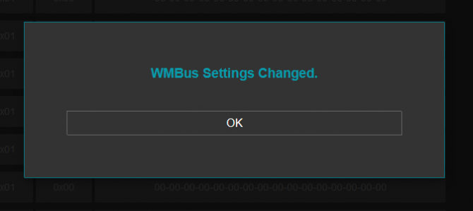
Once the setting has been changed, “Save Configuration” button will be enabled.
After clicking button system will tell if the settings applied successfully or not.
NOTE 1: Settings will be applied once the device is rebooted from web interface or repowered manually.
NOTE 2:
STG has capability to decrypt and convert WMBus data to Modbus protocol for up to 64 devices.
STG Lite Models have capability to decrypt and convert WMBus data to Modbus protocol for up to 20 devices.
D16 Models support up to 20 devices for Modbus conversion and up to 16 devices for decryption. In that version, menu items are different:
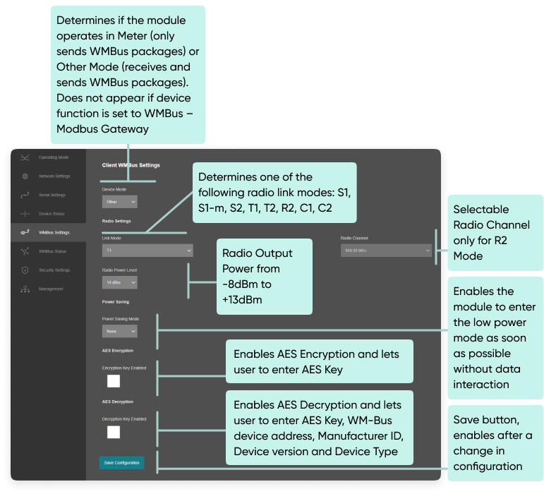
If Enabled STG supports automatic AES-128 encryption and decryption of radio link messages.
There is the chance to configure up to 16 decryption keys for 16 different devices. The keys can be stored in a RAM table together with the complete WM-Bus device address, Manufacturer ID, Device version and Device Type.
Following table shows the RF channel setup. These channels are available in R-Mode for transmissions from Meter to Other devices. The opposite direction is always done in 868.33 MHz (channel 5).
| Channel | Frequency (MHz) |
| 1 | 868,09 MHz |
| 2 | 868,15 MHz |
| 3 | 868,21 MHz |
| 4 | 868,27 MHz |
| 5 | 868,33 MHz |
| 6 | 868,39 MHz |
| 7 | 868,45 MHz |
| 8 | 868,51MHz |
This version of STG is a bidirectional radio device for the 868 MHz frequency band. STG is optimal suited for use in Smart Metering Applications, which are compliant to EN 13757 part 4.
This version of STG supports all link modes according to EN 13757-4: S (stationary), T (frequent transmit), R (frequent receive), C (compact operation). These four main modes are divided into further sub-modes for dedicated applications. All modes are available in web interface. Following table gives an overview over all WM-Bus modes and their physical parameters.
| Mode | Direction | Data Rate | Coding | Frequency | Preamble + Synchronization |
| S1 | Meter => Other | 32,768 kcps | Manchester | 868,3 MHz | 582 chips |
| S1-m | Meter => Other | 32,768 kcps | Manchester | 868,3 MHz | 56 chips |
| S2 | Meter => Other | 32,768 kcps | Manchester | 868,3 MHz | 56 chips |
| Other => Meter | 32,768 kcps | Manchester | 868,3 MHz | 56 chips | |
| T1 | Meter => Other | 100 kcps | 3 out of 6 | 868,95 MHz | 56 chips |
| T2 | Meter => Other | 100 kcps | 3 out of 6 | 868,95 MHz | 56 chips |
| Other => Meter | 32,768 kcps | Manchester | 868,3 MHz | 56 chips | |
| R2 | Meter => Other | 4,8 kcps | Manchester | 868,03 MHz + n*60 kHz | 104 chips |
| Other => Meter | 4,8 kcps | Manchester | 868,33 MHz | 104 chips | |
| C1 | Meter => Other | 100 kcps | NRZ | 868,95 MHz | 64 chips |
| C2 | Meter => Other | 100 kcps | NRZ | 868,95 MHz | 64 chips |
| Other => Meter | 50 kcps | NRZ | 868,525 MHz | 64 chips |
From this menu user may monitor WMBus status and package details as well as WMBus OMS parsed data if available.
The page also helps users to see decryption status of received frames and check STG protocol specific and WMBus protocol specific parameters.
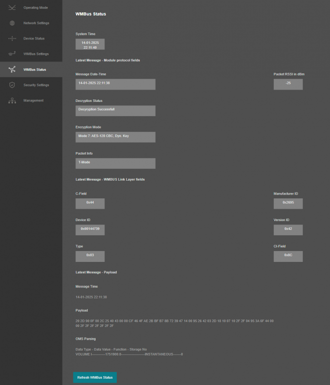
“System Time”: Shows the system of STG.
The page has several parts.
"Latest Message - Module protocol fields":
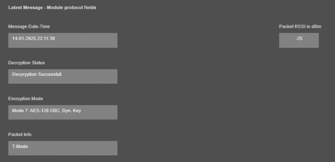
“Message Date-Time”: Shows the system time when latest WMBus frame received.
“Packet RSSI in dBm”: Received Signal Strenght Indicator (dBm) of last package received from WMBus side.
“Decryption Status”: Decryption status of received WMBus frame. Available values are:
“Encryption Mode”: Dedected encryption mode of received WMBus frame. Available values are:
“Packet Info”: Dedected packet type for received WMBus frame.Available values are:
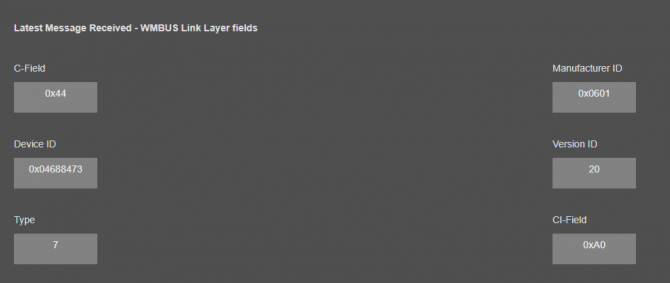
"Latest Message - WMBUS Link Layer fields":
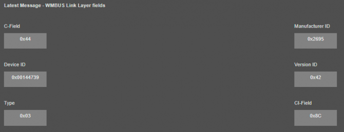
“C-Field”: Control Field of WMBus Frame.
“Manufacturer ID”: Manufacturer ID which is parsed from received WMBus Frame.
“Device ID”: Device ID which is parsed from received WMBus Frame.
“Version ID”: Device version which is parsed from received WMBus Frame.
“CI-Field”: CI-Field of received WMBus Frame.
"Latest Message - Payload":
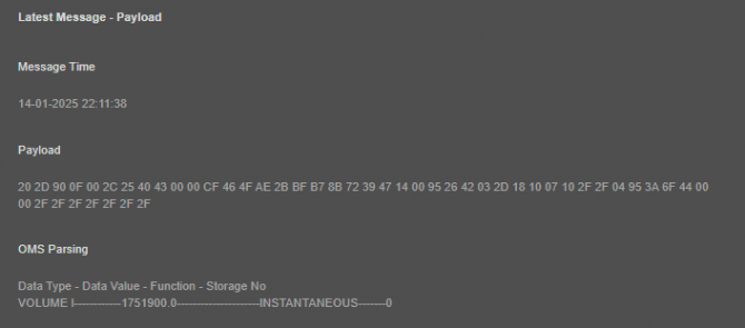
“Message Received Time”: Shows the system time when this specific WMBus frame received.
“Payload” WMBus frame (if decryption is successfull it is also decrypted) after CI-Field part.
“Message Sent Time” Latestw WMBus package received time (based on STG system time)
“Poyload” Latest WMBus package payload in HEX format
“OMS Parsing” OMS parsed data (if available)
Parsed data shared as data blocks. This is valid for both Modbus Frames and web page visualization. Each data block has following values.
details are explained in "Chapter 11: WMBus Data Parsing Format".
After clicking “Refresh WMBus Status” button, system will reload data only and will not reload page. Button will be disabled during reload for an instance. If timeout occurs during the reload, the button will be enabled again with warning of timeout. In normal operation reload of status data will be done immediately.
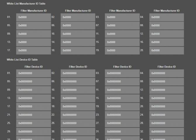
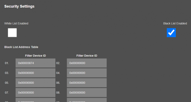
From this menu user may activate WMBus RF communication package filter based on White list (accepted packages from Device ID or Manufacturer ID field of WMBus packages) or Black list (rejected packages from Device ID or Manufacturer ID field of WMBus packages).
Up to 20 entry can be defined as Filtered ManufactrerID
Up to 64 entry can be defined as Filtered Defice ID for standard model (20 entry can be defined for other models) for each filter list.
User can get Manufacturer ID or Device ID values from “WMBus Status” menu page as well.
NOTE: STG Series WMBus Gateways have built in mechanism to get WMBus frames and Auto Configure which is described in "WMBus Settings" menu. Black List can be auto filled by Auto Configuration mechanism, thus user do not have to enter manually.
STG has capability to decrypt and convert WMBus data to Modbus protocol for up to 64 devices.
STG Lite Models have capability to decrypt and convert WMBus data to Modbus protocol for up to 20 devices.
D16 Models support up to 20 devices for Modbus conversion and up to 16 devices for decryption.
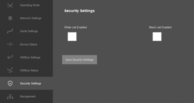
“While List Enabled” Enable to set the White List
“Black List Enabled” Enable to set the Black List
Following settings are available for any of the list:
In this page user can enter decimal values and page will format it to hexadecimal automatically after cursor is moved out of scope.

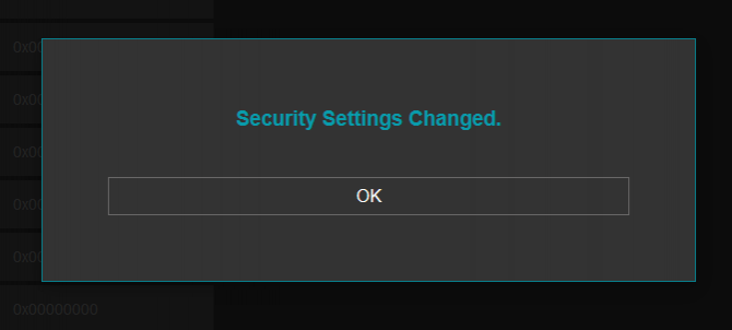
Once the setting has been changed, “Save Configuration” button will be enabled.
After clicking button system will tell if the settings applied successfully or not.
NOTE: Settings will be applied once the device is rebooted from web interface or repowered manually.
From this menu user may change parameters or send command to device.
The device restarts itself every 86400 seconds. (Which means every 24 hours.) There are also timeout restart routines in Server mode during listening clients and in Client Mode trying to connect to the server. ( Both preset to 10 minutes which means device will restart system if fails to connect a server in Client mode or a client do not connect in preset time in Server mode.)
NOTE: NTP is used to syncronize device time after a manual or system triggered restart and it only takes place if NTP time is available and device time difference from NTP time is + or - 24 Hours.
System will also make adjustments if the device time is lagging in minute within 60 minutes time window.
After a firmware change old configuration will be used for minor changes. If a major change occurs system will restore to factory default configuration.
User can change the login information.
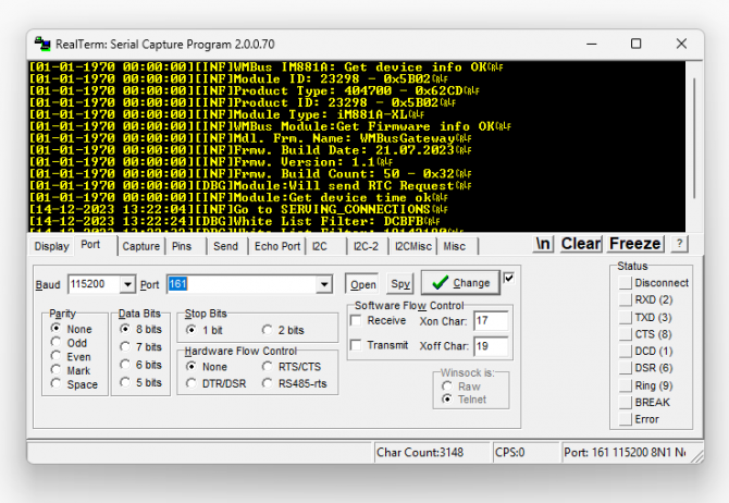
User can change the log level of the device. REDZ STG Series WMBus Gateways series has micro USB or USB Type-C and gives log in 115200 - 8N1 format.
Any terminal program can be used to listen the LOG over USB type-C or micro USB port of the device which is recognized as Virtual COM port in PC.NOTE: Lite models do not have Console port for LOG. They still supports LOG to remote UDP.
User can restore to factory settings and force device to reboot. Factory settings restored by clicking "Restore Factory Configuration" button.

“Set Device Time” This part shows time at page load. Reload page to see updated time. Current local time shows the PC time. User can set the STG time based on shown PC time. The device sets the date and time and reboots.
In "Live Firmware Update" part:
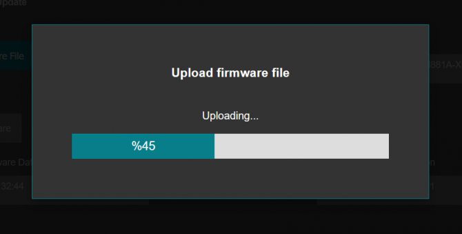
Firmware upgrade is possible only with files that REDZ supplied. Once the file selected, STG shows selected file:

Then “Upload Firmware” button must be clicked. STG will start to upload file and show status on pop up screen.
After successful upload, STG will show "Alternative Firmware Date" and "Alternative Firmware Version" data.
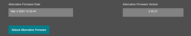
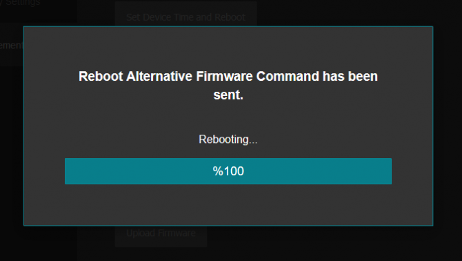
Click "Reboot Alternative Firmware" and STG will reboot with new firmware and show status on screen.
Check firmware details from upper part of main screen please if the update firmware procedure finalized properly

NOTE 1: User must refresh cache of their browser by clicking CTRL+F5 after a succesfull firmware change so that it will force browser to reload web interface (with latest updates/changes).
NOTE 2: In major updates user must also reset device to factory settings.
In "Download / Upload Configuration" part:
User download current configuration of the device to a file or restore a previously defined configuration to device from file.
"Download Current Configuration": Downloads the configuration to a file. It uses "Device Name" for file name and the extensions will be "*.zcfg".
"Download Configuration File": Uploads the configuration from "*.zcfg" file.
In "Log" part:
User may activate Logging and see details of operation. There are different levels of Log with different amount of data.
"None": Logging is closed
"Error": Only errors in systems will be logged
"Info": General info and errors will be logged
"Debug": All details regarding device operation will be logged
If "Console" is selected as output of Log, then micro USB or USB Type-C port of device will be used for logging. Proper cable must be connected and a teminal should be used to receive Log data. As an example "RealTerm" tool can be used.
Simply select COM port and set baud rate 115200 and data type 8N1 and then click open. Device will send log data.
NOTE: Lite models do not have Console port for LOG. They still supports LOG to remote UDP.
If "UDP Server" is selected as output of Log, then proper tool must be used to get log data. User must set "UDP Server IP" and "UDP Server Port". Device will send Log to that address. As an example "Package Sender" tool can be used.
Click "File" and then "Settings". Enable "UDP Server" and set the port. Device will send Log data to UDP server.
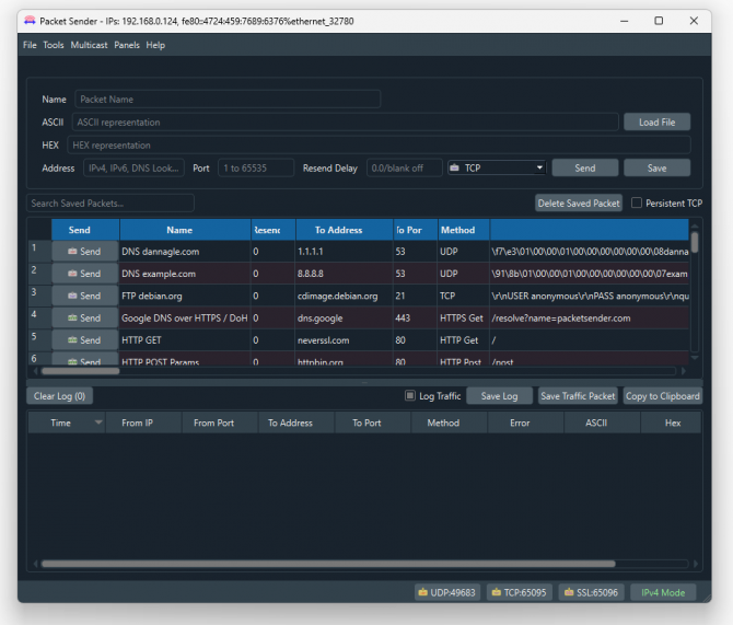
Here is a video example to enable UDP log and receive data via UDP Server software. Video is created with CKL series but applies to all series.
STG decrypts WMBus frames and convert data to Modbus registers Modbus is stored in three parts: Status Block, several Data Blocks depends on number measurements stored in WMBus device and finally the Service Block.
Status Block, 6 Registers:
- WMbus Device ID: 2 Registers
- WMbus Man ID: 1 Register
- WMbus Version: 1 Register
- WMbus Type: 1 Register
- Total Data Count: 1 Register (Represents how many data blocks exists)
Data Block, each 5 Bytes total n bytes:
- Storage Number: 1 Register
- Function Field: 1 Register
- Data Type: 1 Register
- Data Value: 2 Registers
Service Block, 4 Registers:
- Access Number: 1 Register (comes from WMBus packet itself)
- RSSI Value: 1 Register
- Status (from Frame): 1 Register (comes from WMBus packet itself)
- Decrypt Status: 1 Register (status of packet after STG tries to decrypt)
Meaning of numbers in "Decrypt Status" register:
0: "Not Encrypted"
1: "Decyryption Successfull"
2: "No Key Found for WM-Bus Address"
3: "Decryption Mode Not Supported"
4: "Decryption Error, Key Might Be Wrong"
else: "UNKNOWN"
Parsed data is shared by STG as data blocks. This is valid for both Modbus Frames and web page visualization. Each data block has following values:
Here is complete list for Data types available in STG
| Item | Data Type Name | Data Type Value | Data Lenght in bytes stored in MODBUS register | Data Type Format | Data Type description | Range |
| 0 | SPECIAL_FUNC | 0 | 4 | |||
| 1 | ENERGY_WH | 1 | 4 | FLOAT32 | Energy | 0.001Wh to 10000Wh |
| 2 | ENERGY_J | 2 | 4 | FLOAT32 | Energy | 0.001kJ to 10000kJ |
| 3 | VOLUME_M3 | 3 | 4 | FLOAT32 | Volume | 0.001l to 10000l |
| 4 | MASS_KG | 4 | 4 | FLOAT32 | Mass | 0.001kg to 10000kg |
| 5 | POWER_W | 5 | 4 | FLOAT32 | Power | 0.001W to 10000W |
| 6 | POWER_J_H | 6 | 4 | FLOAT32 | Power | 0.001kJ/h to 10000kJ/h |
| 7 | VOLUMEFLOW_M3_H | 7 | 4 | FLOAT32 | Volume Flow | 0.001l/h to 10000l/h |
| 8 | VOLUMEFLOW_M3_M | 8 | 4 | FLOAT32 | Volume Flow ext. | 0.0001l/min to 1000l/min |
| 9 | VOLUMEFLOW_M3_S | 9 | 4 | FLOAT32 | Volume Flow ext. | 0.001ml/s to 10000ml/s |
| 10 | MASSFLOW_KG_H | 10 | 4 | FLOAT32 | Mass flow | 0.001kg/h to 10000kg/h |
| 11 | FLOWTEMPERATURE_C | 11 | 4 | FLOAT32 | Flow Temperature | 0.001°C to 1°C |
| 12 | RETURNTEMPERATURE_C | 12 | 4 | FLOAT32 | Return Temperature | 0.001°C to 1°C |
| 13 | TEMPERATUREDIFF_K | 13 | 4 | FLOAT32 | Temperature Difference | 1mK to 1000mK |
| 14 | EXTERNALTEMP_C | 14 | 4 | FLOAT32 | External Temperature | 0.001°C to 1°C |
| 15 | PRESSURE_Bar | 15 | 4 | FLOAT32 | Pressure | 1mbar to 1000mbar |
| 16 | ON_TIME_S | 16 | 4 | LONG32 | ON time | sec |
| 17 | ON_TIME_M | 17 | 4 | LONG32 | ON time | min |
| 18 | ON_TIME_H | 18 | 4 | LONG32 | ON time | hour |
| 19 | ON_TIME_D | 19 | 4 | LONG32 | ON time | days |
| 20 | OPER_TIME_S | 20 | 4 | LONG32 | Operating time | sec |
| 21 | OPER_TIME_M | 21 | 4 | LONG32 | Operating time | min |
| 22 | OPER_TIME_H | 22 | 4 | LONG32 | Operating time | hour |
| 23 | OPER_TIME_D | 23 | 4 | LONG32 | Operating time | days |
| 24 | AVR_DUR_S | 24 | 4 | LONG32 | Average duration time | sec |
| 25 | AVR_DUR_M | 25 | 4 | LONG32 | Average duration time | min |
| 26 | AVR_DUR_H | 26 | 4 | LONG32 | Average duration time | hour |
| 27 | AVR_DUR_D | 27 | 4 | LONG32 | Average duration time | days |
| 28 | ACT_DUR_S | 28 | 4 | LONG32 | Actuality Duration time | sec |
| 29 | ACT_DUR_M | 29 | 4 | LONG32 | Actuality Duration time | min |
| 30 | ACT_DUR_H | 30 | 4 | LONG32 | Actuality Duration time | hour |
| 31 | ACT_DUR_D | 31 | 4 | LONG32 | Actuality Duration time | days |
| 32 | DURATION_LAST_CUMULATION_H | 32 | 4 | LONG32 | Duration since last cumulation | hour |
| 33 | DURATION_LAST_CUMULATION_D | 33 | 4 | LONG32 | Duration since last cumulation | day |
| 34 | DURATION_LAST_CUMULATION_M | 34 | 4 | LONG32 | Duration since last cumulation | month |
| 35 | DURATION_LAST_CUMULATION_Y | 35 | 4 | LONG32 | Duration since last cumulation | year |
| 36 | BATTERY_OP_TIME_H | 36 | 4 | LONG32 | Battery operation time | hour |
| 37 | BATTERY_OP_TIME_D | 37 | 4 | LONG32 | Battery operation time | day |
| 38 | BATTERY_OP_TIME_M | 38 | 4 | LONG32 | Battery operation time | month |
| 39 | BATTERY_OP_TIME_Y | 39 | 4 | LONG32 | Battery operation time | year |
| 40 | REMAINING_BATTERY_H | 40 | 4 | LONG32 | Remaining battery time | hour |
| 41 | REMAINING_BATTERY_D | 41 | 4 | LONG32 | Remaining battery time | day |
| 42 | REMAINING_BATTERY_M | 42 | 4 | LONG32 | Remaining battery time | month |
| 43 | REMAINING_BATTERY_Y | 43 | 4 | LONG32 | Remaining battery time | year |
| 44 | MODEL_VERSION | 44 | 4 | LONG32 | ||
| 45 | HUMIDITY_Percent | 45 | 4 | LONG32 | ||
| 46 | TIME_POINT_DATE | 46 | 4 | LONG32 | 2 bytes date (in 4 bytes register), Data Type G | YY:MM:DD |
| 47 | TIME_POINT_DATE_TIME | 47 | 4 | LONG32 | 4 bytes time and date, Data Type F | YY:MM:DD HH:MM:SS |
| 48 | BATTERY_CHANGE_DATE_TIME | 48 | 4 | LONG32 | 4 bytes time and date, Data Type F | YY:MM:DD HH:MM:SS |
| 49 | FABRICATION_NO | 49 | 4 | LONG32 | ||
| 50 | SPECIAL_SUPPLIER_INFO | 50 | 4 | LONG32 | ||
| 51 | REVERSEFLOW_VOLUME | 51 | 4 | FLOAT32 | Volume | 0.001l/h to 10000l/h |
| 52 | ERROR_FLAGS | 52 | 4 | LONG32 | ||
| 53 | HUMIDITY_Relative | 53 | 4 | FLOAT32 | ||
| 54 | DIMENSIONLESS | 54 | 4 | LONG32 | ||
| 55 | VERSION | 55 | 4 | LONG32 | ||
| 56 | VOLUME_UNCORRECTED | 56 | 4 | FLOAT32 | Volume | 0.001l/h to 10000l/h |
| 57 | ENERGY_RESRVD_GJ | 57 | 4 | FLOAT32 | Energy | |
| 58 | REVERSEFLOW_POWER | 58 | 4 | FLOAT32 | ||
| 59 | REVERSEFLOW_ENERGY | 59 | 4 | FLOAT32 | ||
| 60 | VOLTAGE_PHASE_L1 | 60 | 4 | FLOAT32 | ||
| 61 | VOLTAGE_PHASE_L2 | 61 | 4 | FLOAT32 | ||
| 62 | VOLTAGE_PHASE_L3 | 62 | 4 | FLOAT32 | ||
| 63 | VOLTAGE | 63 | 4 | FLOAT32 | ||
| 64 | FORWARDFLOW_VOLUME | 64 | 4 | FLOAT32 | Volume | 0.001l/h to 10000l/h |
| 65 | NOT_IMPLEMENTED | 65 | 4 | LONG32 | ||
| 66 | UNIT_FOR_HCA | 66 | 4 | LONG32 | ||
| 67 | RESERVED | 67 | 4 | LONG32 | ||
| 68 | ENHANCED_ID | 68 | 4 | LONG32 | ||
| 69 | BUS_ADDRESS | 69 | 4 | LONG32 |
Parsed data is shared by STG as data blocks as the details are given above. There are also 4 registers at the end of each frame (service registers) to show Access Number, RSSI value, Status value of frame and Decryption Status.
Here is an example Modbus data frame ( without Modbus frame header part and CRC part for Modbus RTU)
1A00144739269500420037000100000001000349D5DAE0002DFFCD
1A: 1 byte frame length, which is 1Ah and which is 26 in decimal and WMBus data shared as blocks
00144739: 4 bytes of WMBus device id
2695: 2 bytes of WMBus device manufacturer id
0042: 2 bytes of WMBus device version
0037: 2 bytes of WMBus device type
0001: 1 byte of Data count value. Data shared in blocks and this value shows how many blocks are there
00000001000349D5DAE0: Each data blocks has following values in 6 registers and 12 bytes
Storage Number (of data from meter) - 2 bytes
Function Field (of data from meter) - 2 bytes
Data Type (STG uses this value to identify type of Data that is shown above) - 2 bytes, Data Type is Volume in this example
Data Value (float data based on Data Type in this example) - 4 bytes, 1751900.0 in this example
002D: 1 byte of Access Number value as unsigned integer. 45 in this example.
FFCD: 1 byte of RSSI value as signed integer. -51 in this example.
STG series WMBus Gateways can get WMBus frames, decrypt the data and share data as Modbus values.
As a first step user should select "Device Function" under Operating Mode page:
"WMBus - Modbus TCP Gateway (and MQTT Publisher)"
Or
"WMBus - Modbus RTU Gateway (and MQTT Publisher)"
In this example we have selected "WMBus - Modbus TCP Gateway (and MQTT Publisher)" and saved configuration. Reboot command sent to device under "Management" menu.
"Modbus Scheduler Settings" is still empty in this stage.
STG will listen WMBus frames.
Click "Refresh Auto Config List" button under "WMBus Settings" menu. When this button clicked, STG will show received frames with latest RSSI values for all WMBus devices since the device powered up. If there is no RSSI value, that means STG did not receive any WMBus frame yet, user may wait and click button again.
If a line has notation "Recently Dedected" on the right side of entyr and framed with green line, that means this WMBus frame received and this device is not in configuration (or not in Black List), user may select it to "Add to Config" or "Add to Black List" based on needs.
If "Add to Black List" checked, after clicking "Save Configuration", STG will save this device id under "Black List Table" (and enables list by checking "Black List Enabled" checkbox, if not enabled already) under "Security Settings" menu. This entry also will be freed up from decryption list to be used for new coming frames.
NOTE: User must enter AES keys manually.
After all settings are done, click "Save Configuration" button. That process will save configuration and also put the device id to Modbus list ( and black List if it is used) automatically thus ease up configuration process dramatically.
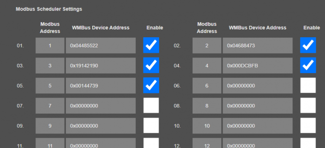
Here is "Modbus Scheduler Settings" view under "Operating Mode" menu after saving settings.
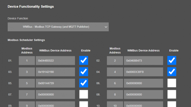
Each WMBus device is separate MODBUS device so user should matched Manufacturing IDs of field devices with selected Modbus Device Addresses. Then user should enable the entry that STG will expect the WMBus data and share info as Modbus register.
Here is "Black List Address Table" view under "Security Settings" menu after saving settings.
NOTE: All values in "AES-128 Decryption List", "Modbus Scheduler Settings" and "Black List Address Table" can also be entered/changed mnaually. In that case user may get help from "WMBus Status" menu to get WMBus frame details as follows:
If WMbus – Modbus RTU Gateway is set, user can make serial interface settings under menu Serial Settings.
If WMbus – Modbus TCP Gateway is set, user can change Modbus TCP Port under menu Network Settings.
STG series WMbus – Modbus TCP/RTU Gateway devices can get WMBus OMS data and convert those to Modbus registers. Users or field devices can read WMBus data over Modbus registers. Here are basic rules:
- Each wMBUS device is separate MODBUS slave
Slave ID is possible to configure in STG web page "Operating Mode" in table "Modbus Scheduler Settings" column "Modbus address"
- MODBUS data is stored in three parts: Status Block, several Data Blocks depends of number measurements stored in WMBus device and finally the Service Block
Number of words needed to read all register is possible after counting length of data blocks. For example, if in status block "data count" value is equal to 2 you have to read 6+(2*5 (16))+4 words from address 0
- To restrict number of WMBUS devices it is possible use "White" or "Black" list of WMBus devices
See "Security Settings" in STG web configuration page
- To Decrypt WMBus devices you have to fill "AES-128 Decryption List"
See " WMBus Settings" in STG web configuration page
- Current WMBus frame details is possible to find in " WMBus Status" page
See " WMBus Status" in STG web configuration page
- Current Modbus frame details is possible to find in "Device Status" page
See "Device Status" in STG web configuration page
MODBUS data is stored in three parts: Status Block, several Data Blocks depends on number measurements stored in WMBus device and finally the Service Block.
Status Block, 6 Registers:
- WMbus Device ID: 2 Registers
- WMbus Man ID: 1 Register
- WMbus Version: 1 Register
- WMbus Type: 1 Register
- Total Data Count: 1 Register (Represents how many data blocks exists)
Data Block, each 5 Bytes total n bytes:
- Storage Number: 1 Register
- Function Field: 1 Register
- Data Type: 1 Register
- Data Value: 2 Registers
NOTE: Please check "Chapter 11: WMBus Data Parsing Format" to see details of Data Types used by STG
Service Block, 4 Registers:
- Access Number: 1 Register (comes from WMBus packet itself)
- RSSI Value: 1 Register
- Status (from Frame): 1 Register (comes from WMBus packet itself)
- Decrypt Status: 1 Register (status of packet after STG tries to decrypt)
In this example "Marcom OPC Server Modnet" software is used to read Modbus values and Modbus TCP protocol is used.
Any Modbus software can read following values with similar settings.
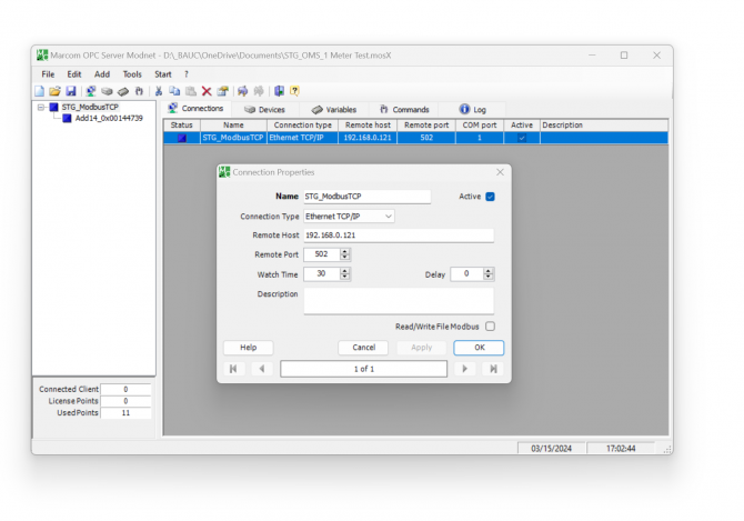
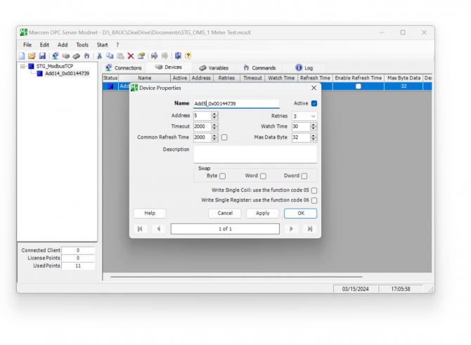
Enter TCP IP and TCP Port of STG for connection. In our example TCP IP is "192.168.0.121" and port is "502".
Then enter device Modbus ID.
In this example we want to read device id "0x00144739" and this is mapped with modbus address "5".
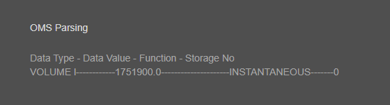
Then checked parsed data from "WMBus Status" page to see the parsed data. We will read 1 data blcok in this example.
NOTE: If data type part show "NOT IMPLEMENTED", data is not implemented as a valid type in STG and cannot be read via Modbus and that is not count in data blocks.
User may contact our company if that data is needed to be implemented and read via Modbus.
Enter register details and data types baesd on read data, in this example we will read Status Block, Data Block and Service Block (all blocks)
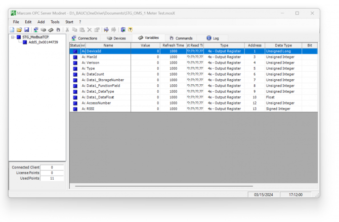
Status Block, 6 Registers:
- WMbus Device ID: 2 Registers, unsigned long
- WMbus Man ID: 1 Register, unsigned integer
- WMbus Version: 1 Register, unsigned integer
- WMbus Type: 1 Register, unsigned integer
- Total Data Count: 1 Register, unsigned integer
1 Data Block:
- Storage Number: 1 Register, unsigned integer
- Function Field: 1 Register, unsigned integer
- Data Type: 1 Register, unsigned integer
- Data Value: 2 Registers, Float 32 bytes
NOTE: Please check "Chapter 11: WMBus Data Parsing Format" to see details of Data Types used by STG.
In this example, "Data Type" is "VOLUME l".
Service Block, 4 Registers:
- Access Number: 1 Register (comes from WMBus packet itself)
- RSSI Value: 1 Register
- Status (from Frame): 1 Register (comes from WMBus packet itself)
- Decrypt Status: 1 Register (status of packet after STG tries to decrypt)
Save settings and click "Start OPC Server" (or F9) button to read values.
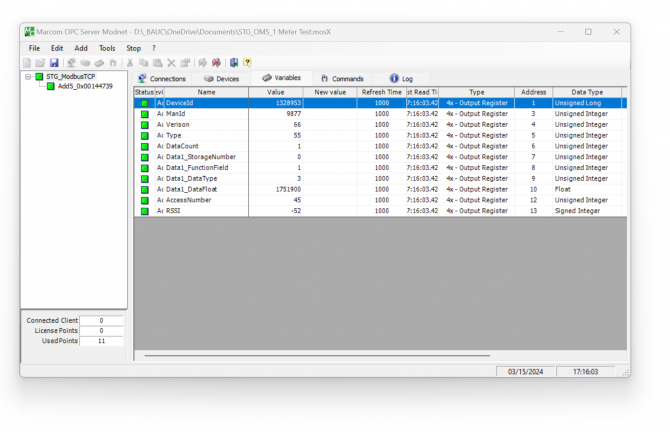
Here is log for sent and received frames

Received frame details are as follows:
00540000001D: 6 bytes of Modbus TCP protocol header
05: 1 byte of Modbus adress
03: 1 byte fo Modbus Function Code
1A: 1 byte data length, which is 1Ah and which is 26 in decimal and WMBus data shared as blocks
00144739: 4 bytes of WMBus device id
2695: 2 bytes of WMBus device manufacturer id
0042: 2 bytes of WMBus device version
0037: 2 bytes of WMBus device type
0001: 1 byte of Data count value. Data shared in blocks and this value shows how many blocks are there
00000001000349D5DAE0: Each data blocks has following values in 6 registers and 12 bytes
Storage Number (of data from meter) - 2 bytes
Function Field (of data from meter) - 2 bytes
Data Type (STG uses this value to identify type of Data that is shown in previous example) - 2 bytes, Data Type is Volume in this example
Data Value (float data based on Data Type in this example) - 4 bytes, 1751900.0 in this example
002D: 1 byte of Access Number value as unsigned integer. 45 in this example.
FFCD: 1 byte of RSSI value as signed integer. -51 in this example.
NOTE: This example is given for Modbus TCP Frame. Modbus RTU frame will be similar in following manner :
STG Series WMBus Gateways can get Wireless MBus (WMBus) frames, decrypt them and parse them. Field devices or applications can get meter WMBus data mapped to Modbus registers via Modbus TCP (or Modbus RTU). Simultaneously all meter data can be sent to MQTT Server. STG has capability to decrypt and convert WMBus data to Modbus protocol as well as send data to MQTT Server for up to 64 devices in standard models (up to 20 WMBus devices in other models).
Enter meter reading details to STG and make sure all readings are ok.
Please follow details regarding settings and put into operation of STG based on explanations in "Chapter 12: WMBus OMS – Modbus Conversion Example" for adding WMBus meter details and parsing WMBus meter data.
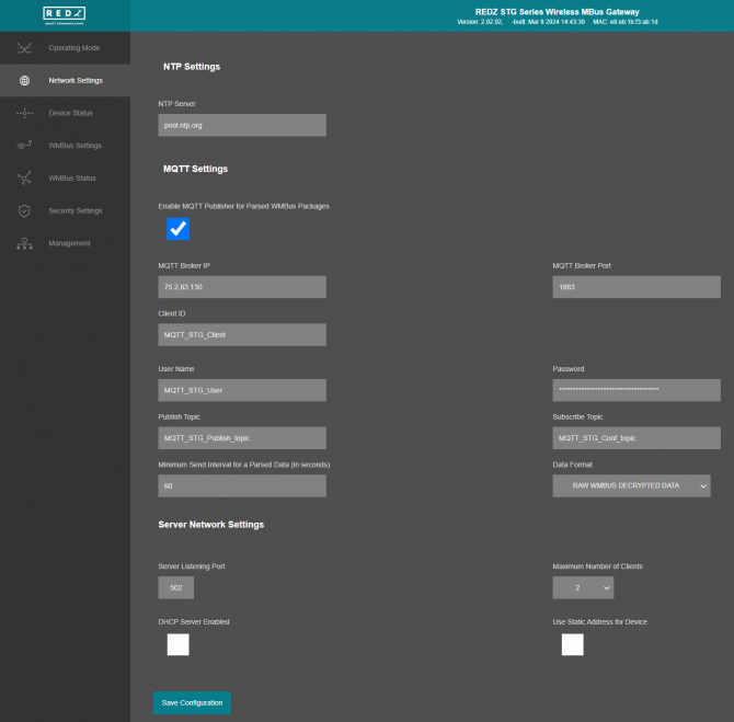
Then go to "Network Settings" menu and "Enable MQTT Publisher for Parsed WMBus Packages" part.
In our example we will use "https://tago.io/" as MQTT Server.
Go to MQTT server panel and click "Add Device" to add STG to MQTT Server. We will also get password after adding device.
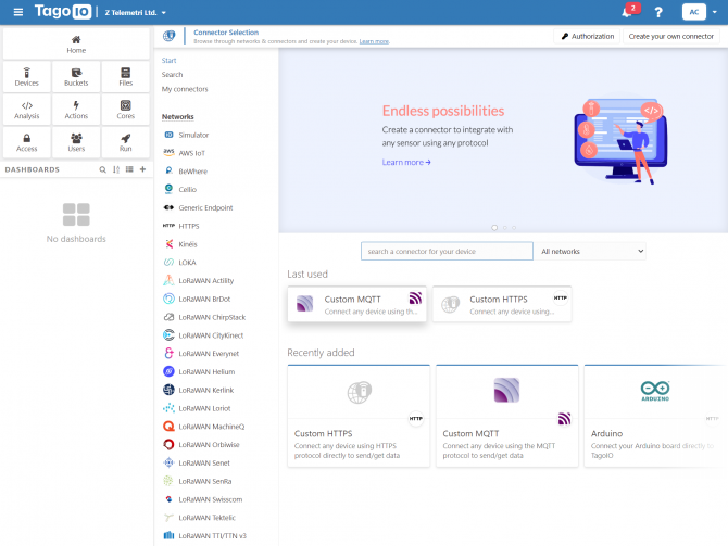
Select "Custom MQTT".
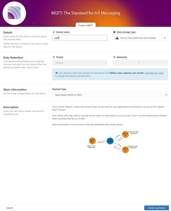
Then enter "Device name" in pop up screen and click "Create My Device".
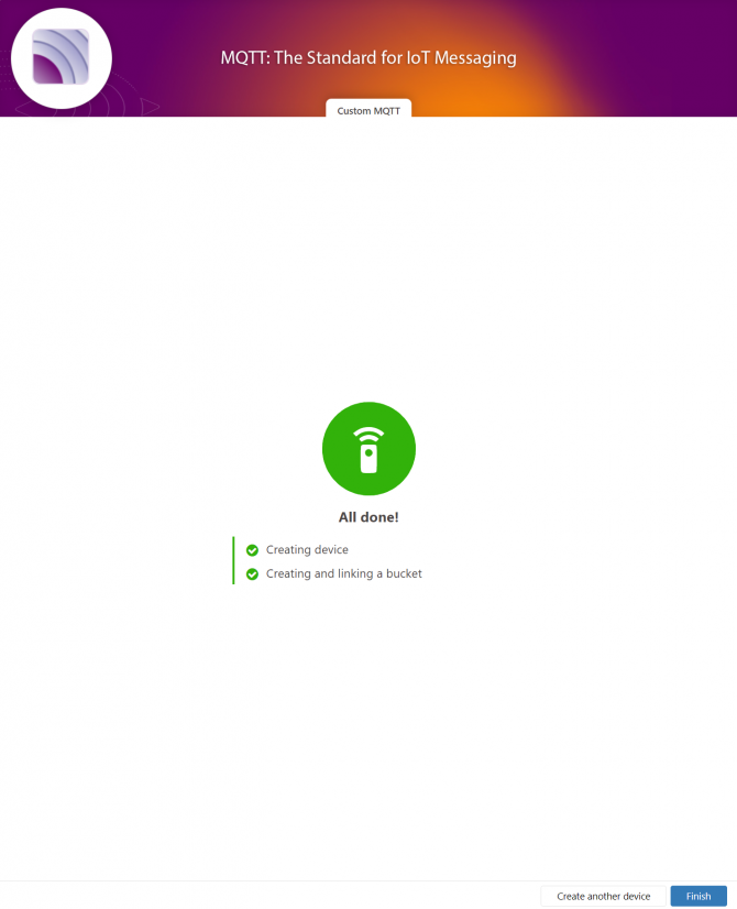
Click "Finish" when all done.
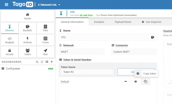
Once the device is created, click "Copy Token" button. This will copy password value.
Then go back to STG and enter that value as password and click "Save Configuration" button.

"MQTT Broker IP": TCP IP of the MQTT Server. User must enter IP value
75.2.83.130 is IP of "https://tago.io/" web address.
"MQTT Broker Port": TCP Port of the MQTT Server.
1883 is TCP Port of "https://tago.io/" web address.
"Client ID": MQTT Publisher client id. Default is MQTT_STG_Client.
Maximum length for this field is 32.
"User Name": MQTT Publisher user name. This must be entered based on MQTT server settings.
Maximum length for this field is 64.
"Password": MQTT Publisher password. This must be entered based on MQTT server settings.
Maximum length for this field is 48.
"Publish Topic": MQTT Publisher topic value. Default is MQTT_STG_Publish_topic.
Maximum length for this field is 32.
"Subscribe Topic": MQTT Publisher subscribe topic value. Default is MQTT_STG_Subscribe_topic.
Maximum length for this field is 32.
"Minimum Send Interval for a Parsed Data (in seconds)": Minimum value to send meter data to MQTT Server. This time is the minimum time to send data to server, if WMBus meter sends frames in longer periods then it will be basis of the sending interval.
"Data Format": Options for how data is shared by STG with MQTT server. There are 2 options:
RAW WMBUS DECRYPTED DATA
PARSED DATA AS OBJECTS
PARSED DATA AS MODBUS FRAME
When selected as "Raw WMBus Decrypted Data", STG will share WMBus frame as it is but decrypted as follows as an example:
MQTT message shows STG device name, device id, NTP time and data itself
Data has values of WMBus Device Id, Manufacturer Id, Device Version, Device Type, RSSI Value of recevied signal, Access Number value and Decrypted frame Data Block.
When selected as "Parsed Data As Objects", STG will share WMBus data as parsed objects as follows as an example:
MQTT message shows STG device name, device id, NTP time and data itself
Data has values of WMBus Device Id, Manufacturer Id, Device Version, Device Type, RSSI Value of recevied signal, Access Number value.
Parsed Data is shared in blocks and Data Count value shows how many blocks are there.
In this example there is 1 block
{\"S\":\"0\",\"F\":\"1\",\"T\":\"3\",\"V\":\"1751900.0\"}
Here are explanations:
S: Storage Number (of data from meter)
F: Function Field (of data from meter)
T: Data Type (STG uses this value to identify type of Data)
V: Data Value (can be float or UINT - 4 byte data, matched with Data Type)
NOTE: Parsed data shared as data blocks. This is valid for both Modbus Frames and web page visualization. Each data block has following values:
- Data Type specified by STG
- Data Value (can be a float or long value)
- Function, available values are:
INSTANTANEOUS, MAXIMUM, MINIMUM or ERROR STATE
- Data Storage Number as an integer
details are explained in "Chapter 11: WMBus Data Parsing Format".
When selected as "Parsed Data As Modbus Frame", STG will share WMBus data as Modbus like frame as follows as an example:
MQTT message shows STG device name, device id, NTP time and data itself
Data has values of WMBus Device Id, Manufacturer Id, Device Version, Device Type, RSSI Value of recevied signal, Access Number value.
Parsed Data is shared in Modbus like frame, in this example as follows.
1A00144739269500420037000100000001000349D5DAE0002DFFCD
1A: 1 byte frame length, which is 1Ah and which is 26 in decimal and WMBus data shared as blocks
00144739: 4 bytes of WMBus device id
2695: 2 bytes of WMBus device manufacturer id
0042: 2 bytes of WMBus device version
0037: 2 bytes of WMBus device type
0001: 1 byte of Data count value. Data shared in blocks and this value shows how many blocks are there
00000001000349D5DAE0: Each data blocks has following values in 6 registers and 12 bytes
Storage Number (of data from meter) - 2 bytes
Function Field (of data from meter) - 2 bytes
Data Type (STG uses this value to identify type of Data that is shown in previous example) - 2 bytes, Data Type is Volume in this example
Data Value (float data based on Data Type in this example) - 4 bytes, 1751900.0 in this example
002D: 1 byte of Access Number value as unsigned integer. 45 in this example.
FFCD: 1 byte of RSSI value as signed integer. -51 in this example.
NOTE: Parsed data shared as data blocks. This is valid for both Modbus Frames and web page visualization. Each data block has following values:
- Data Type specified by STG
- Data Value (can be a float or long value)
- Function, available values are:
INSTANTANEOUS, MAXIMUM, MINIMUM or ERROR STATE
- Data Storage Number as an integer
details are explained in "Chapter 11: WMBus Data Parsing Format".
There are also 4 registers at the end of each frame (service registers) to show Access Number, RSSI value, Status value of frame and Decryption Status.
When all settings are done click "Save Configuration".
Go back to "https://tago.io/" panel and click "Live Inspector" for the STG and click "Play button".
Data will be shown in real time.
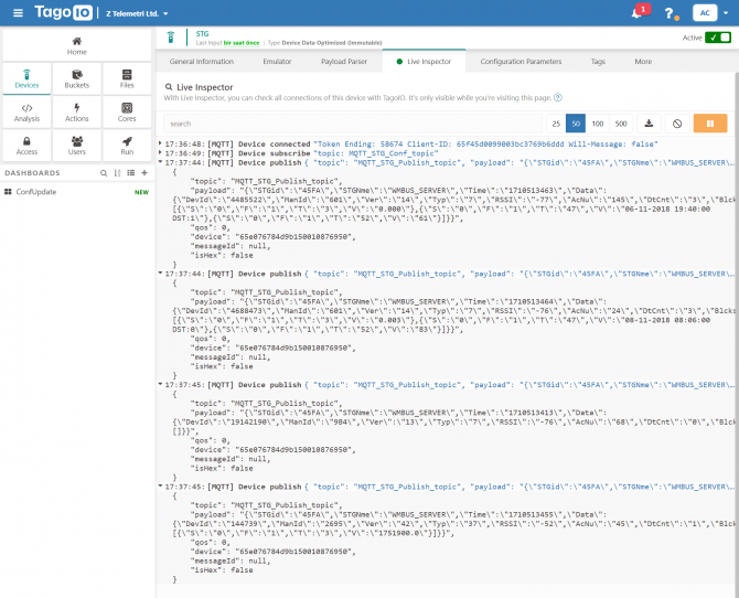
User has to parse and use that parsed data for visualization (for graphs for example) for their application. That is beyond scope of STG usage.
STG Series WMBus Gateways have built in mechanism to get WMBus frames and Auto Configure. AES Decryption, Modbus Adress mapping and Black list items can be auto filled by Auto Configuration mechanism, thus user do not have to enter manually each item besides AES Key. STG has capability to decrypt and convert WMBus data to Modbus protocol for up to 64 devices in standard models (up to 20 WMBus devices in other models and AES decryption is limited to 16 devices in D16 models).
STG Series WMBus Gateways can receive WMBus OMS packages and convert them to Modbus TCP packages. This way WMBus packages of up to 64 meters (Lite Models and D16 models support up to 20 WMBus devices) can directly be collected on a remote or local Data Server or RTU device as Modbus registers and can be used for other applications.
STG "Device function" is set as "WMBus – Modbus TCP Gateway (and MQTT Publisher)". Manufacturing IDs of field devices can be listed with related Modbus addresses. If needed decryption list can be set and White/Black list can be enabled. Received WMBus OMS messages will be converted to Modbus Registers and field or remote Modbus TCP devices can query that data from related Modbus addresses. The decrypted and parsed data can also be sent to MQTT Server in simultaneoulsy.
Here is an example video for this application (this video follows steps described in Chapter 12. WMBus OMS – Modbus Conversion Example) :
STG Series WMBus Gateways can receive WMBUS packages, decrypt data and parse. All parsed data can be sent to MQTT server for web based applications in several different formats. This way WMBus packages of up to 64 meters (Lite Models and D16 models support up to 20 WMBus devices) can directly be sent to a local or remote MQTT Server in one of predefined format and data can be analyzed and can be used for monitoring in server applications.

STG "Device function" is set as "WMBus Decoder/Parser and MQTT Publisher" or "WMBus – Modbus TCP Gateway (and MQTT Publisher)".
Here is an example video for this application (this video follows steps described in Chapter 13. MQTT Communication Example) :
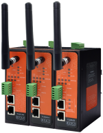
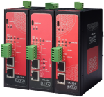
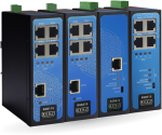
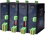
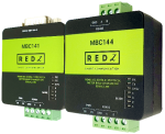
STG154: 868MHz WMBus – Modbus TCP/RTU Gateway with MQTT Publisher, 2x 10/100 T(x) ETH ports, 1 x RS232 & 1 x RS485, 5-48V ( max. 60V) DC Power Input
STG254: 868MHz WMBus – Modbus TCP/RTU Gateway with MQTT Publisher, 2x 10/100 T(x) ETH ports, 1 x RS232 & 1 x RS485, 100 - 240V AC (120 – 370V DC), 50Hz to 60Hz AC Power Input
STG655: 868MHz WMBus – Modbus TCP/RTU Gateway with MQTT Publisher, 2x 10/100 T(x) ETH ports + 1 x BPL (Broadband Power Line) Link, 1 x RS232 & 1 x RS485, 3 Phase AC Power Input, 110V–240V/50-60Hz
STG154 - D16: 868MHz WMBus – Modbus TCP/RTU Gateway with MQTT Publisher, 2x 10/100 T(x) ETH ports, 1 x RS232 & 1 x RS485, 5-48V ( max. 60V) DC Power Input
STG254 - D16: 868MHz WMBus – Modbus TCP/RTU Gateway with MQTT Publisher, 2x 10/100 T(x) ETH ports, 1 x RS232 & 1 x RS485, 100 - 240V AC (120 – 370V DC), 50Hz to 60Hz AC Power Input
STG655 - D16: 868MHz WMBus – Modbus TCP/RTU Gateway with MQTT Publisher, 2x 10/100 T(x) ETH ports + 1 x BPL (Broadband Power Line) Link, 1 x RS232 & 1 x RS485, 3 Phase AC Power Input, 110V–240V/50-60Hz
STG154 - Lite: 868MHz WMBus – Modbus TCP/RTU Gateway with MQTT Publisher, 1x 10/100 T(x) ETH port and 1 x RS485, 9-36V ( max. 40V) DC Power Input
NOTE:
STG has capability to decrypt and convert WMBus data to Modbus protocol for up to 64 devices.
STG Lite Models have capability to decrypt and convert WMBus data to Modbus protocol for up to 20 devices.
D16 Models support up to 20 devices for Modbus conversion and up to 16 devices for decryption.Those version model names differantiated with -D16 extension.
| Model | MQTT Connectivity | Up to 64 WMBus device data decryption and parse | Up to 16 WMBus device data decryption and up to 20 WMBus device data parse | Up to 20 WMBus device data decryption and parse | Decryption Mode 5, Mode 7, Mode 128 and Custom | Decryption Mode 5 | 9-36V (max. 40V) DC Power Input | 5-48V (max. 60V) DC Power Input | 100 - 240V AC (120 – 370V DC), 50Hz to 60Hz AC Power Input | 3 Phase AC Power input, 110V–240V/50-60Hz AC Power Input | BPL (Broadband Power Line) Link |
| STG154 | X | X | X | X | |||||||
| STG254 | X | X | X | X | |||||||
| STG655 | X | X | X | X | X | ||||||
| STG154 - D16 |
X | X | X | X | |||||||
| STG254 - D16 |
X | X | X | X |
|||||||
| STG655 - D16 |
X | X | X | X | X |
||||||
| STG154- Lite | X | X | X | X |


THIS SITE USES COOKIES
Various types of cookies are used on our website (and on all other digital platforms including mobile applications).
View our new THE INFORMATIVE TEXT ON LPPD AND PRIVACY here.
Google Analytics
Analytical cookies help us to improve our website by collecting and reporting information on its usage.
Google AdWords and Remarketing
We use marketing cookies to help us improve the relevancy of advertising campaigns you receive.
I have read the above articles
 download