Various types of cookies are used on our website (and on all other digital platforms including mobile applications). View our new THE INFORMATIVE TEXT ON LPPD AND PRIVACY here. Google Analytics Analytical cookies help us to improve our website by collecting and reporting information on its usage. Google AdWords ve Remarketing We use marketing cookies to help us improve the relevancy of advertising campaigns you receive.
I have read the above articles
 INDEX
INDEX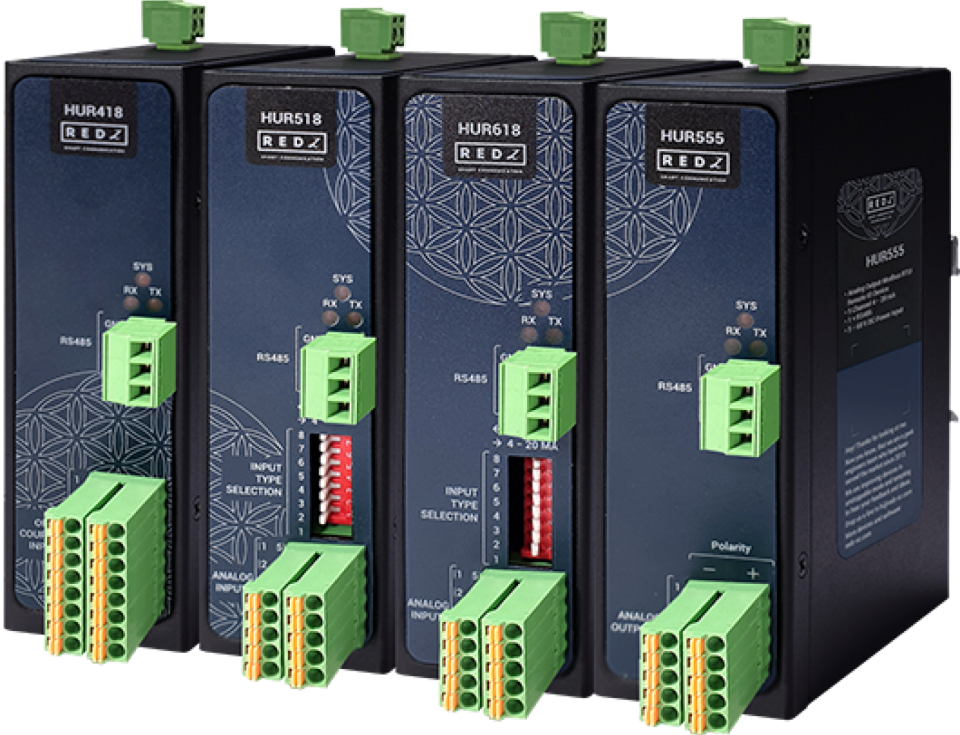
HUR Series Modbus RTU Remote Input/Output (I/O) Devices are designed for facilities of rugged industry and infrastructure and perform various features such as wide temperature, wide range power input range... etc. HUR Series Modbus RTU Remote I/O Devices offers different I/O options, which provide greater flexibility and are compatible with many different applications that makes them the perfect choice for establishing a cost-effective remote I/O system.
HUR Series Modbus RTU Remote Input/Output (I/O) Devices support up to 8 I/O, any of Analog Input, Digital Input, Analog Output or Digital Output options can be selected. All I/O data can be read via Modbus RTU. I/O data can also be controlled through Modbus RTU protocol via commands for output models.
HUR Series Modbus RTU Remote I/O Devices has several versions with different I/O options such as:
8 Channel 5-275V AC-DC, 100mA Digital Optocoupler Output
8 Channel Digital 5Amps 250VAC/30VDC Relay Output
8 Channel 12-275V AC-DC, 60mA Digital Optocoupler Input
8 Channel 0-10V and 0-20mA Selectable Analog Input
5 Channel 4-20mA Analog Output
All versions can be selected with 100 - 240V AC (120 – 370V DC), 50Hz to 60Hz AC input or 5-48V ( max. 60V) DC wide range power input. HUR Series Modbus RTU Remote I/O Devices communicate in Modbus RTU protocol with 115200 8N1 data type over standard RS485 serial line.
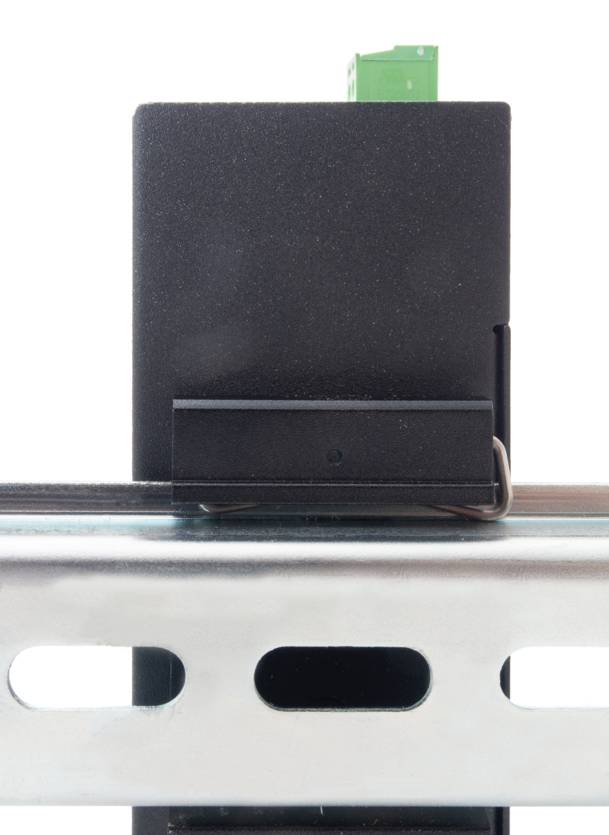
Each device has a Din-Rail kit on rear panel. The Din-Rail kit helps device to fix on the Din-Rail. Slant the switch and mount the metal spring to Din-Rail.
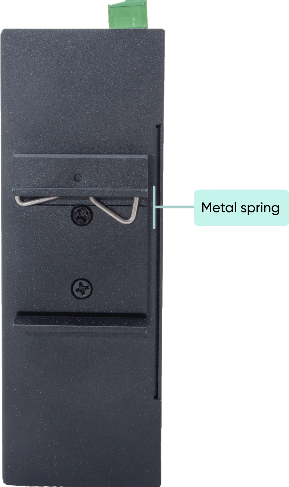
Then Push the switch toward the Din-Rail until you heard a “click” sound.
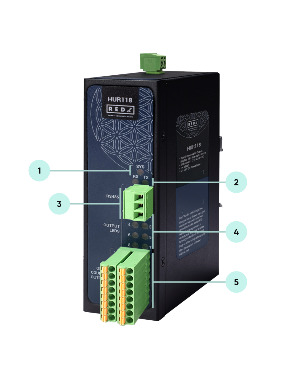
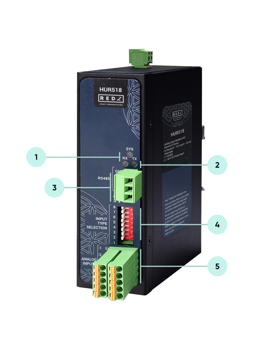
System LED: Flashes during normal operation.
Activity LEDs
Tx LED: Flashes when the device sends Modbus RTU packages.
Rx LED: Flashes when the device receives Modbus RTU packages.
Terminal Connector for 2 wire RS485 connection and GND.
| Pin Number | Description |
| 1 | GND |
| 2 | B |
| 3 | A |
Output Status LEDs: Shows which pin is ON (conducting) and OFF (cut off) for Digital Outputs
| LED Number | LED Status and Description |
| 1 |
ON: Output ON, circuit is closed and running OFF: Output is OFF, circuit is open and cut off |
| 2 | |
| 3 | |
| 4 | |
| 5 | |
| 6 | |
| 7 | |
| 8 |
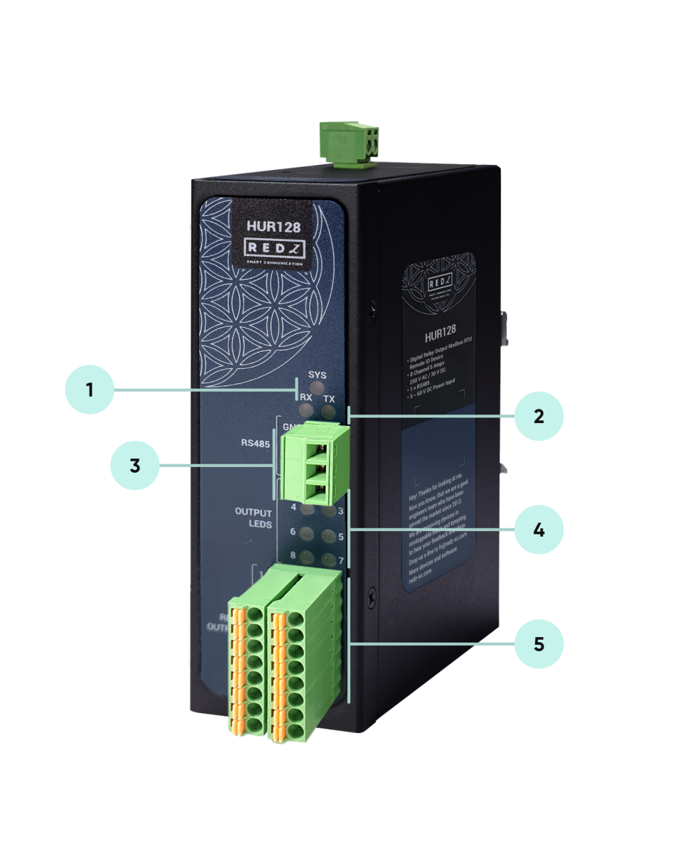
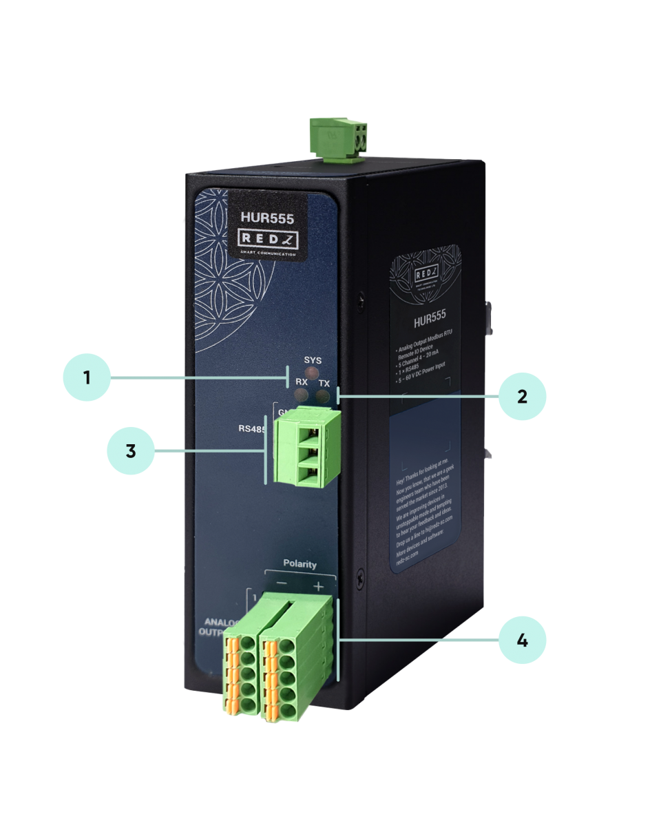
System LED: Flashes during normal operation.
Activity LEDs
Tx LED: Flashes when the device sends Modbus RTU packages.
Rx LED: Flashes when the device receives Modbus RTU packages.
Terminal Connector for 2 wire RS485 connection and GND.
| Pin Number | Description |
| 1 | GND |
| 2 | B |
| 3 | A |
Output Status LEDs: Shows which pin is ON (conducting) and OFF (cut off) for Digital Outputs.
| LED Number | LED Status and Description |
| 1 |
ON: Output ON, circuit is closed and running OFF: Output is OFF, circuit is open and cut off |
| 2 | |
| 3 | |
| 4 | |
| 5 | |
| 6 | |
| 7 | |
| 8 |
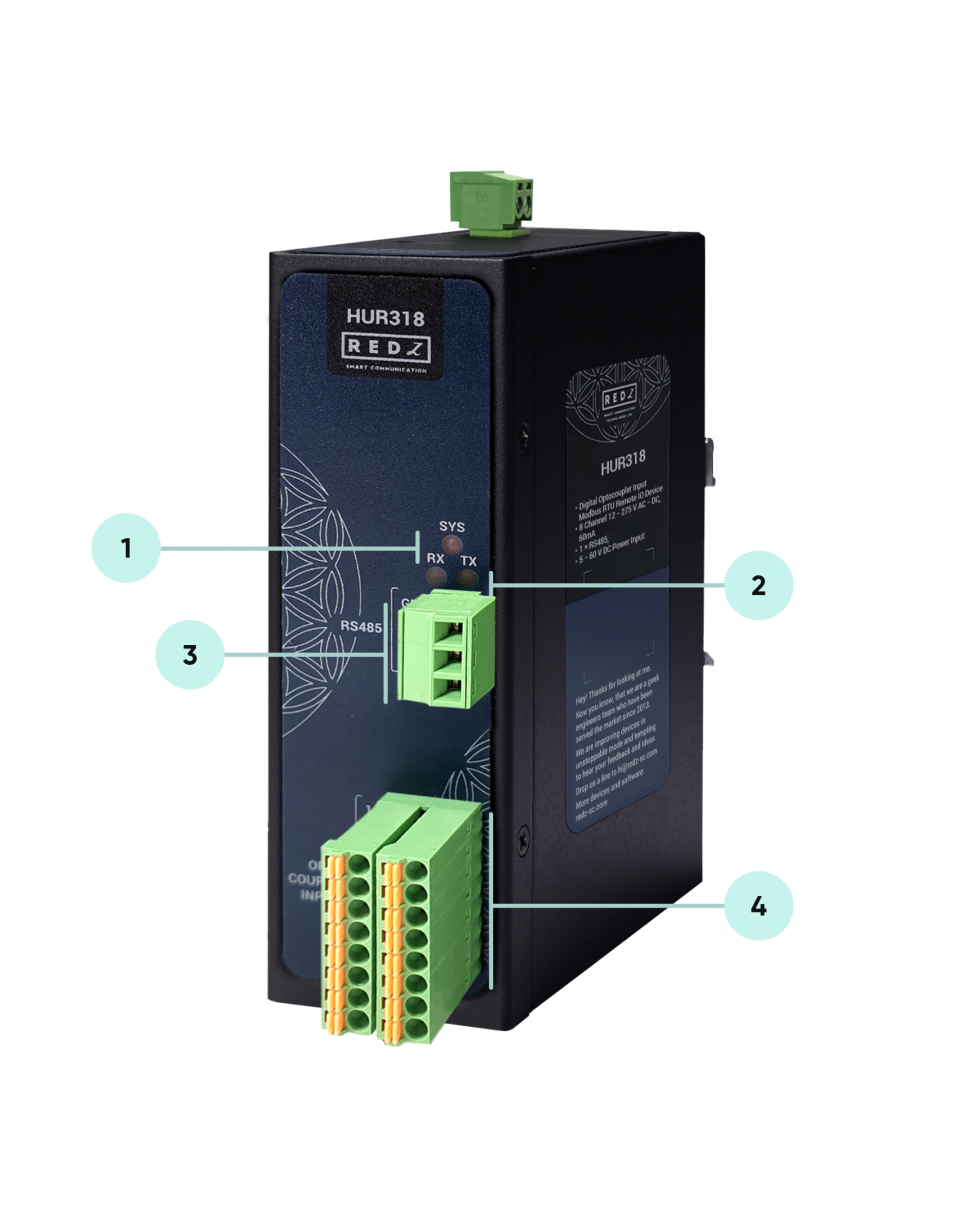
System LED: Flashes during normal operation.
Activity LEDs
Tx LED: Flashes when the device sends Modbus RTU packages.
Rx LED: Flashes when the device receives Modbus RTU packages.
Terminal Connector for 2 wire RS485 connection and GND.
| Pin Number | Description |
| 1 | GND |
| 2 | B |
| 3 | A |
System LED: Flashes during normal operation.
Activity LEDs
Tx LED: Flashes when the device sends Modbus RTU packages.
Rx LED: Flashes when the device receives Modbus RTU packages.
Terminal Connector for 2 wire RS485 connection and GND.
| Pin Number | Description |
| 1 | GND |
| 2 | B |
| 3 | A |
Operation Mode Selection Switches for Analog Inputs: 8 pin Switch to select operation mode of each Analog Input either 0-10V or 0-20mA.
| Switch Number | Switch Status and Description |
| 1 |
Switch Position ON: 4-20mA analog input expected Switch Position OFF: 0-10V analog input expected |
| 2 | |
| 3 | |
| 4 | |
| 5 | |
| 6 | |
| 7 | |
| 8 |
System LED: Flashes during normal operation.
Activity LEDs
Tx LED: Flashes when the device sends Modbus RTU packages.
Rx LED: Flashes when the device receives Modbus RTU packages.
Terminal Connector for 2 wire RS485 connection and GND.
| Pin Number | Description |
| 1 | GND |
| 2 | B |
| 3 | A |
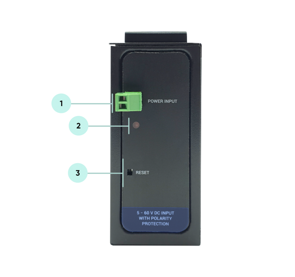
Power Input DC: 5-48V (max. 60V) DC. Polarity protected so that the power input can be connected in any direction.
Power LED: Turns ON when there is power in device.
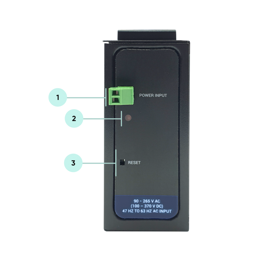
Power Input AC: 100 - 240V AC (120 – 370V DC), 50Hz to 60Hz AC input
Power LED: Turns ON when there is power in device.
HUR Series Modbus RTU Remote I/O Devices can be used in different scenarios. Usages are not limited to that examples and user may create their own usage scenario.
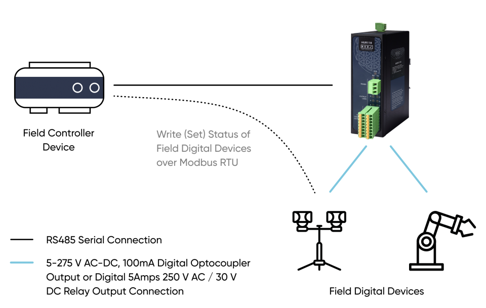
HUR Series Modbus RTU Remote I/O Devices can be connected to Digital field devices and Field Control or Central Software Control System can write parameters such as Turn ON a light or Turn on a valve. Communication protocol will be Modbus RTU. Outputs will be 5-275V AC-DC, 100mA Digital Optocoupler Output or 5Amperes 250VAC/30VDC Relay Output. Following devices can be used for this application:
HUR118 and HUR218 with 8 Channel 5-275V AC-DC, 100mA Digital Optocoupler Output
HUR128 and HUR228 with 8 Channel Digital 5Amps 250VAC/30VDC Relay Output
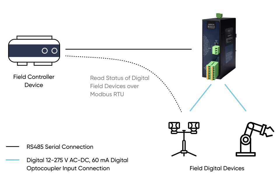
HUR Series Modbus RTU Remote I/O Devices can be connected to Digital field devices and Field Control or Central Software Control System can read status of the field devices such as status of light or status of a circuit breaker. Communication protocol will be Modbus RTU. Inputs will be 12-275V AC-DC, 60mA Digital Optocoupler Input. Following devices can be used for this application:
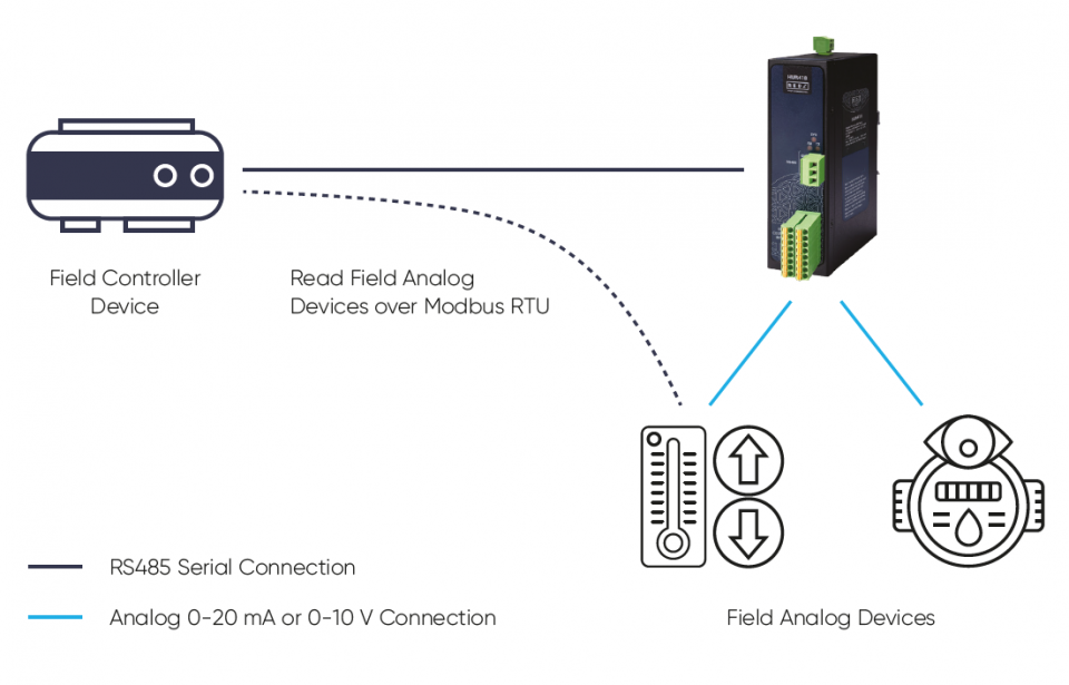
HUR Series Modbus RTU Remote I/O Devices can be connected to Analog field devices and Field Control or Central Software Control System can read status of the field devices such as status temperature sensors or pressure sensors. Communication protocol will be Modbus RTU. Inputs will be 0-10V and 0-20mA Selectable Analog Input. Following devices can be used for this application:
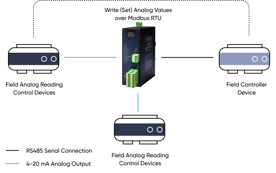
HUR Series Modbus RTU Remote I/O Devices can be connected to field control devices and Field Main Control or Central Software Control System can write Analog Values for that secondary field control devices such as duplicating or generating an analog value like flow of a fluid value for a field control device. Communication protocol will be Modbus RTU. Outputs will be 4-20mA Analog Output. Following devices can be used for this application:
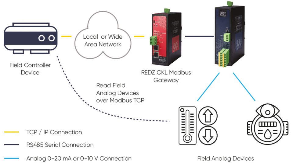
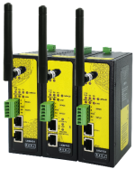
REDZ CKL Series Modbus, Serial to Ethernet Gateways can connect field serial device to TCP/IP Network to control that devices remotely with a software on a server or with a TCP/IP device. For example, with CKL Series Modbus, Serial to Ethernet Gateways, users can connect HUR Series Modbus RTU Remote I/O Devices and create a system to read that devices remotely.
CKL Gateway devices in field configured for Transparent Communication and act as TCP Server to Serial Device Gateway. HUR Series Modbus RTU Remote I/O Devices are connected over RS485 serial line and communication data type and baud rate fixed.
HUR Series Modbus RTU Remote I/O Devices can be connected to Analog field devices and Field Control or Central Software Control System can read status of the field devices such as status temperature sensors or pressure sensors.
Communication protocol will be Modbus TCP thanks to CKL connection.
Inputs will be 0-10V and 0-20mA Selectable Analog Input. Following devices can be used for this application:
CKL154: Modbus, Serial to Ethernet Gateway, 2x 10/100 T(x) ETH ports, 1 x RS232 & 1 x RS485, 5-60V DC Power Input
CKL254: Modbus, Serial to Ethernet Gateway, 2x 10/100 T(x) ETH ports, 1 x RS232 & 1 x RS485, 90 - 265V AC (100 – 370V DC), 47Hz to 63Hz AC Power Input
CKL655: Modbus, Serial to Ethernet Gateway, 2x 10/100 T(x) ETH ports + 1 x BPL (Broadband Power Line) Link, 1 x RS232 & 1 x RS485, 3 Phase AC Power Input, 110V–240V/50-60Hz
(User needs to create a Broadband Powerline Network with REDZ devices by using CKL or BSB series in order to use that model)
HUR518 and HUR618 with 8 Channel 0-10V and 0-20mA Selectable Analog Input
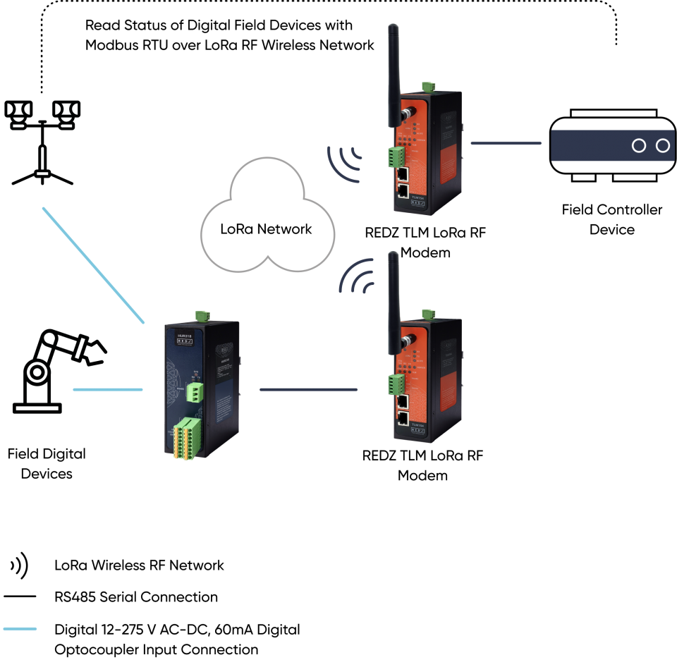
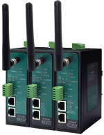
REDZ TLM Series LoRa Based RF Gateways can link RS232 and/or RS485 serial devices and create a network over RF. For example, with TLM Series LoRa Based RF Gateways users can connect HUR Series Modbus RTU Remote I/O Devices with Field Control Devices over RF network and create wireless automation.
TLM act as Serial to LoRa RF Gateway configured as Client Mode (Client mode suggested to use in serial communication since TCP server capabilities will not be used), Serial communication is enabled and settings are done based on field device.
HUR Series Modbus RTU Remote I/O Devices can be connected to Digital field devices and Field Control or Central Software Control System can read status of the field devices such as status of light or status of a circuit breaker.
Communication protocol will be Modbus RTU over Lora RF Network thanks to TLM connection.
Inputs will be 12-275V AC-DC, 60mA Digital Optocoupler Input. Following devices can be used for this application:
TLM154: 868MHz LoRa based gateway, 2x 10/100 T(x) ETH ports, 1 x RS232 & 1 x RS485, 5-60V DC Power Input
TLM254: 868MHz LoRa based gateway, 2x 10/100 T(x) ETH ports, 1 x RS232 & 1 x RS485, 90 - 265V AC (100 – 370V DC), 47Hz to 63Hz AC Power Input
TLM655: 868MHz LoRa based gateway, 2x 10/100 T(x) ETH ports + 1 x BPL (Broadband Power Line) Link, 1 x RS232 & 1 x RS485, 3 Phase AC Power Input, 110V–240V/50-60Hz
(User needs to create a Broadband Powerline Network with REDZ devices by using TLM or BSB series in order to use that model)
HUR318 and HUR418 with 8 Channel 12-275V AC-DC, 60mA Digital Optocoupler Input
HUR Series Modbus RTU Remote I/O Devices communicate in Modbus RTU protocol with 115200 8N1 data type over standard RS485 serial line. HUR Series Modbus RTU Remote I/O Devices has several versions with different I/O options and different version uses different Modbus Function codes:
HUR118 and HUR218 with 8 Channel 5-275V AC-DC, 100mA Digital Optocoupler Output
Uses Function Code 0x01: Read Coil Status to read status of output values
Uses Function Code 0x03: Read Holding Registers to read device parameters and status of monitoring values
Uses Function Code 0x05: Force Single Coil to set value of individual output values
Uses Function Code 0x06: Preset Single Register to set value of individual device parameter values
Uses Function Code 0x0F: Force Multiple Coils to set value of all output values at once
HUR128 and HUR228 with 8 Channel Digital 5Amps 250VAC/30VDC Relay Output
Uses Function Code 0x01: Read Coil Status to read status of output values
Uses Function Code 0x03: Read Holding Registers to read device parameters and status of monitoring values
Uses Function Code 0x05: Force Single Coil to set value of individual output values
Uses Function Code 0x06: Preset Single Register to set value of individual device parameter values
Uses Function Code 0x0F: Force Multiple Coils to set value of all output values at once
HUR318 and HUR418 with 8 Channel 12-275V AC-DC, 60mA Digital Optocoupler Input
Uses Function Code 0x02: Read Input Status to read status of input values
Uses Function Code 0x03: Read Holding Registers to read device parameters and status of monitoring values
Uses Function Code 0x06: Preset Single Register to set value of individual device parameter values
HUR518 and HUR618 with 8 Channel 0-10V and 0-20mA Selectable Analog Input
Uses Function Code 0x03: Read Holding Registers to read device parameters and status of monitoring values
Uses Function Code 0x04: Read Input Registers to read input values
Uses Function Code 0x06: Preset Single Register to set value of individual device parameter values
HUR555 and HUR655 with 5 Channel 4-20mA Analog Output
Uses Function Code 0x03: Read Holding Registers to read device parameters and status of monitoring values
Uses Function Code 0x06: Preset Single Register to set value of individual device register values and device parameter values
HUR Series Digital Output Modbus RTU Remote I/O Devices
HUR118 and HUR218 with 8 Channel 5-275V AC-DC, 100mA Digital Optocoupler Output
HUR128 and HUR228 with 8 Channel Digital 5Amps 250VAC/30VDC Relay Output
Has following Modbus Functions:
Uses Function Code 0x01: Read Coil Status to read status of output values
Uses Function Code 0x03: Read Holding Registers to read device parameters and status of monitoring values
Uses Function Code 0x05: Force Single Coil to set value of individual output values
Uses Function Code 0x06: Preset Single Register to set value of individual device parameter values
Uses Function Code 0x0F: Force Multiple Coils to set value of all output values at once
Request
This command is requesting the ON/OFF status of discrete outputs # 01 to 08
from the slave device with address 1.
01 01 0001 0008 6C0C
01: The Slave Address (01 hex = address 1 )
01: The Function Code 1 (read Coil Status)
0001: The Data Address of the first output to read.
( 0001 hex = 01)
0008: The total number of outputs requested. (08hex = 8)
6C0C: The CRC (cyclic redundancy check) for error checking.
Response
01 01 01 19 9042
01: The Slave Address (01 hex = address 1 )
01: The Function Code 1 (read Coil Status)
01: The number of data bytes to follow (8 Outputs / 8 bits per byte = 1 byte)
19: Outputs 1 - 8 (0001 1001)
9042: The CRC (cyclic redundancy check).
The more significant bits contain the higher output variables. This shows that outputs 8-7-6 is off (0) and 5-4 is on (1), outputs 3-2 is off (0) and 1 is on (1).
HUR Series Digital Output Modbus RTU Remote I/O Devices has following settings that can be read:
| Register Number | Definition | Explanation | Modbus Address (Decimal) | Modbus Address (Hexadecimal) | Data Type |
| 1 | Modbus Address |
HUR Series Modbus RTU Remote I/O Device Address for Communication. Default Address is 0x01 |
128 | 0x80 | Unsigned Integer (UInt16) |
| 2 | Save Data Before Auto Restart Option |
HUR Series Modbus RTU Remote I/O Device restart itself in an automated manner to keep stability. Duration for each restart is 24 hours. This option is to save Output Values before restart and apply it after successful auto restart. It can be either Enabled (0x01) or Disabled (0x00) Default Value is 0x01: Enabled |
129 | 0x81 | Unsigned Integer (UInt16) |
| 3 | Use Custom Output Values on Power On |
HUR Series Modbus RTU Remote I/O Device can accept user to set output values for next Power On. It is like keeping a constant configuration, so that Users can alter register values of outputs and when the device is Powered On, outputs will be in action based on configuration. User must also set the relevant registers after Enabling this option. It can be either Enabled (0x01) or Disabled (0x00) Default Value is 0x01: Disabled |
130 | 0x82 | Unsigned Integer (UInt16) |
Request
This command is requesting the content of device parameter holding registers # 40128 to 40130 from the slave device with address 1.
01 03 0080 0003 0423
01: The Slave Address (01hex = address 1)
03: The Function Code 3 (read Holding Registers)
0080: The Data Address of the first register requested.
( 0080hex = 128 )
0003: The total number of registers requested. (read 3 registers 40128 to 40130)
0423: The CRC (cyclic redundancy check) for error checking.
Response
01 03 06 0001 0001 0000 4D75
01: The Slave Address (01hex = address 1)
03: The Function Code 3 (read Holding Registers)
06: The number of data bytes to follow (3 registers x 2 bytes each = 6 bytes)
0001: The contents of register 40128
0001: The contents of register 40129
0000: The contents of register 40130
4D75: The CRC (cyclic redundancy check).
HUR Series Digital Output Modbus RTU Remote I/O Devices has following monitoring parameters that can be read:
| Register Number | Definition | Explanation | Modbus Address (Decimal) | Modbus Address (Hexadecimal) | Data Type |
| 1 | Modbus Read Counter | This value increments 1 after successful sending a Modbus Response Package from HUR device side. | 160 | 0xA0 | Unsigned Long (UInt32) |
| 2 | Second Counter |
Increments 1 every second since the device is powered up. Device restarts after 24 hours (86400 seconds) |
162 | 0xA2 | Unsigned Long (UInt32) |
| 3 | FW Version Original |
Gives device firmware info when the device is sold from stock. Includes version and build date 4 byte data example: 0x1A37E401: 0x1A: DAY = 26 0x3: MONTH = 3 0x7E4: YEAR = 2020 0x01: VERSION = 1 |
164 | 0xA4 | Unsigned Long (UInt32) |
| 4 | FW Version Upgraded |
Gives device firmware info and it differs from FW Original version if the device firmware changed in the field. Includes version and build date 4 byte data example: 0x1B37E401: 0x1B: DAY = 27 0x3: MONTH = 3 0x7E4: YEAR = 2020 0x01: VERSION = 1 |
166 | 0xA6 | Unsigned Long (UInt32) |
Request
This command is requesting the content of device parameter holding registers # 40160 to 40166 from the slave device with address 1.
01 03 00A0 0008 442E
01: The Slave Address (01hex = address 1)
03: The Function Code 3 (read Holding Registers)
00A0: The Data Address of the first register requested.
( 00A0 hex = 160 )
0008: The total number of registers requested. (read 4 registers each holding Unsigned Int32 values)
442E: The CRC (cyclic redundancy check) for error checking.
Response
01 03 10 0000000D 00000AB4 1A37E401 1B37E401 004D
01: The Slave Address (01hex = address 1)
03: The Function Code 3 (read Holding Registers)
10: The number of data bytes to follow (4 registers x 4 bytes each = 16 bytes)
0000000D: The contents of register 40160
00000AB4: The contents of register 40162
1A37E401: The contents of register 40164
1B37E401: The contents of register 40166
004D: The CRC (cyclic redundancy check).
HUR Series Modbus RTU Remote I/O Device can accept user to set output values for next Power On. It is like keeping a constant configuration on outputs, so that Users can alter register values of outputs and when the device is Powered On, outputs will be in action based on configuration. Those registers can be read with Function Code 3.
| Register Number | Definition | Explanation | Modbus Address (Decimal) | Modbus Address (Hexadecimal) | Data Type |
| 1 | Output 1 | Custom Output Value on Power On for Output 1 if option 3 (Use Custom Output Values on Power On ) is Enabled | 65 | 0x41 | Unsigned Integer (UInt16) |
| 2 | Output 2 | Custom Output Value on Power On for Output 1 if option 2 (Use Custom Output Values on Power On ) is Enabled | 66 | 0x42 | Unsigned Integer (UInt16) |
| 3 | Output 3 | Custom Output Value on Power On for Output 3 if option 3 (Use Custom Output Values on Power On ) is Enabled | 67 | 0x43 | Unsigned Integer (UInt16) |
| 4 | Output 4 | Custom Output Value on Power On for Output 4 if option 3 (Use Custom Output Values on Power On ) is Enabled | 68 | 0x44 | Unsigned Integer (UInt16) |
| 5 | Output 5 | Custom Output Value on Power On for Output 5 if option 3 (Use Custom Output Values on Power On ) is Enabled | 69 | 0x45 | Unsigned Integer (UInt16) |
| 6 | Output 6 | Custom Output Value on Power On for Output 6 if option 3 (Use Custom Output Values on Power On ) is Enabled | 70 | 0x46 | Unsigned Integer (UInt16) |
| 7 | Output 7 | Custom Output Value on Power On for Output 7 if option 3 (Use Custom Output Values on Power On ) is Enabled | 71 | 0x47 | Unsigned Integer (UInt16) |
| 8 | Output 8 | Custom Output Value on Power On for Output 8 if option 3 (Use Custom Output Values on Power On ) is Enabled | 72 | 0x48 | Unsigned Integer (UInt16) |
Request
This command is reading the contents of output configuration registers
to the slave device with address 01.
01 03 0040 0008 45D8
01: The Slave Address (01 hex = address 1 )
03: The Function Code 3 (read Holding Registers)
0040: The Data Address of the first register requested.
( 0040 hex = 64)
0008: The total number of registers requested. (read 8 registers each holding Unsigned Int16 values. Digital Output device has 8 outputs and uses 8 registers)
45D8: The CRC (cyclic redundancy check) for error checking.
Response
01 03 10 0001 0001 004B 0000 0001 0001 0001 0001 EA3D
01: The Slave Address (01hex = address 1)
03: The Function Code 3 (read Holding Registers)
10: The number of data bytes to follow (8 registers x 2 bytes each = 16 bytes)
0001 : The contents of register 40041
0001 : The contents of register 40042
004B : The contents of register 40043
0000 : The contents of register 40044
0001 : The contents of register 40045
0001 : The contents of register 40046
0001 : The contents of register 40047
0001 : The contents of register 40048
EA3D : The CRC (cyclic redundancy check).
For Example, for output 3, value is set to : Hexadecimal 004B which is 75 Decimal
Digital Output Value = 1 - ON
For Example, for output 4, value is set to : Hexadecimal 0000 which is 0 Decimal
Digital Output Value = 0 - OFF
For Example, for output 5, value is set to : Hexadecimal 0005 which is 5 Decimal
Digital Output Value = 1 - ON
Request
This command is writing the contents of discrete output # 7 to ON in the slave device with address 1.
01 05 0006 FF00 6C3B
01: The Slave Address (01 hex = address 1 )
05: The Function Code 5 (Force Single Coil)
0006: The Data Address of the coil. (output# 7 = 7 hex)
( 0007 hex = 7 = output # 7 )
FF00: The value to write ( FF00 = ON, 0000 = OFF )
4E8B: The CRC (cyclic redundancy check) for error checking.
Response
The normal response is an echo of the query, returned after the coil has been written.
01 05 0006 FF00 6C3B
01: The Slave Address (01 hex = address 1 )
05: The Function Code 5 (Force Single Coil)
0006: The Data Address of the coil. (output# 7 - 1 = 6 = 06 hex)
FF00: The status written ( FF00 = ON, 0000 = OFF )
4E8B: The CRC (cyclic redundancy check) for error checking.
HUR Series Digital Output Modbus RTU Remote I/O Devices has following settings that can be altered:
| Register Number | Definition | Explanation | Modbus Address (Decimal) | Modbus Address (Hexadecimal) | Data Type |
| 1 | Modbus Device Address |
HUR Series Modbus RTU Remote I/O Device Address for Communication. Default Address is 0x01 |
128 | 0x80 | Unsigned Integer (UInt16) |
| 2 | Save Data Before Auto Restart Option |
HUR Series Modbus RTU Remote I/O Device restart itself in an automated manner to keep stability. Duration for each restart is 24 hours. This option is to save Output Values before restart and apply it after successful auto restart. It can be either Enabled (0x01) or Disabled (0x00) Default Value is 0x01: Enabled |
129 | 0x81 | Unsigned Integer (UInt16) |
| 3 | Use Custom Output Values on Power On |
HUR Series Modbus RTU Remote I/O Device can accept user to set output values for next Power On. It is like keeping a constant configuration, so that Users can alter register values of outputs and when the device is Powered On, outputs will be in action based on configuration. User must also set the relevant registers after Enabling this option. It can be either Enabled (0x01) or Disabled (0x00) Default Value is 0x01: Disabled |
130 | 0x82 | Unsigned Integer (UInt16) |
Request
This command is writing the contents of device parameter register # 40130
to the slave device with address 01.
01 06 0082 0001 E822
01: The Slave Address (01 hex = address 1 )
06: The Function Code 6 (Preset Single Register)
0082: The Data Address of the register.
( 0082 hex = 130 )
0001: The value to write ( Enable option 3 (Use Custom Output Values on Power On ) )
E822: The CRC (cyclic redundancy check) for error checking.
Response
The normal response is an echo of the query, returned after the register contents have been written.
01 06 0082 0001 E822
01: The Slave Address (01 hex = address 1 )
06: The Function Code 6 (Preset Single Register)
0082: The Data Address of the register.
0001: The value written (Option 3 (Use Custom Output Values on Power On ) Enabled)
E822: The CRC (cyclic redundancy check) for error checking.
HUR Series Digital Output Modbus RTU Remote I/O Devices also has following registers that can be altered and used if option 3 in settings part is Enabled
| Register Number | Definition | Explanation | Modbus Address (Decimal) | Modbus Address (Hexadecimal) | Data Type |
| 1 | Register 1 | Custom Output Value on Power On for Output 1 if option 3 (Use Custom Output Values on Power On ) is Enabled | 65 | 0x41 | Unsigned Integer (UInt16) |
| 2 | Register 2 | Custom Output Value on Power On for Output 2 if option 3 (Use Custom Output Values on Power On ) is Enabled | 66 | 0x42 | Unsigned Integer (UInt16) |
| 3 | Register 3 | Custom Output Value on Power On for Output 3 if option 3 (Use Custom Output Values on Power On ) is Enabled | 67 | 0x43 | Unsigned Integer (UInt16) |
| 4 | Register 4 | Custom Output Value on Power On for Output 4 if option 3 (Use Custom Output Values on Power On ) is Enabled | 68 | 0x44 | Unsigned Integer (UInt16) |
| 5 | Register 5 | Custom Output Value on Power On for Output 5 if option 3 (Use Custom Output Values on Power On ) is Enabled | 69 | 0x45 | Unsigned Integer (UInt16) |
| 6 | Register 6 | Custom Output Value on Power On for Output 6 if option 3 (Use Custom Output Values on Power On ) is Enabled | 70 | 0x46 | Unsigned Integer (UInt16) |
| 7 | Register 7 | Custom Output Value on Power On for Output 7 if option 3 (Use Custom Output Values on Power On ) is Enabled | 71 | 0x47 | Unsigned Integer (UInt16) |
| 8 | Register 8 | Custom Output Value on Power On for Output 8 if option 3 (Use Custom Output Values on Power On ) is Enabled | 72 | 0x48 | Unsigned Integer (UInt16) |
Request
This command is writing the contents of device parameter register # 40043
to the slave device with address 01.
01 06 0042 0001 E81E
01: The Slave Address (01 hex = address 1 )
06: The Function Code 6 (Preset Single Register)
0042: The Data Address of the register.
( 0042 hex = 66 , + 40001 offset = register #40043 )
0001: The value to write ( Set Register 3 for Output 3)
E81E: The CRC (cyclic redundancy check) for error checking.
Response
The normal response is an echo of the query, returned after the register contents have been written.
01 06 0042 0001 E81E
01: The Slave Address (01 hex = address 1 )
06: The Function Code 6 (Preset Single Register)
0042: The Data Address of the register.
0001: The value to write (Register 3 for Output 3 is Set)
E81E: The CRC (cyclic redundancy check) for error checking.
Request
This command is writing the contents of a series of 8 discrete outputs from #1 to #8
to the slave device with address 17.
01 0F 0001 0008 01 98 C2FF
01: The Slave Address (11 hex = address17 )
0F: The Function Code 15 (Force Multiple Coils, 0F hex = 15 )
0001: The Data Address of the first output.
(0001 hex = 1)
0008: The number of outputs to write ( 08 hex = 8 )
01: The number of data bytes to follow (8 outputs / 8 bits per byte = 1 byte)
98: Outputs 1 - 8 (1001 1000)
BF0B: The CRC (cyclic redundancy check) for error checking.
The more significant bits contain the higher output variables. This shows that outputs 8-5-4 is on (1) and 7-6-3-2-1 is off (0).
Response
01 0F 0001 0008 05CD
01: The Slave Address (11 hex = address17 )
0F: The Function Code 15 (Force Multiple Coils, 0F hex = 15 )
0001: The Data Address of the first output.
(0001 hex = 1)
0008: The number of outputs to write ( 08 hex = 8 )
05CD: The CRC (cyclic redundancy check) for error checking.
HUR Series Digital Output Modbus RTU Remote I/O Devices
Has following Modbus Functions:
Uses Function Code 0x02: Read Input Status to read status of input values
Uses Function Code 0x03: Read Holding Registers to read device parameters and status of monitoring values
Uses Function Code 0x06: Preset Single Register to set value of individual device parameter values
Request
This command is requesting the ON/OFF status of discrete inputs # 10001 to 10008
from the slave device with address 1.
01 02 0001 0008 280C
01: The Slave Address (01 hex = address 1)
02: The Function Code 2 (read Input Status)
0001: The Data Address of the first input to read.
( 0001hex = 1 )
0008: The total number of inputs requested. (8 hex = 8, inputs 1 to 8 )
280C: The CRC (cyclic redundancy check) for error checking.
Response
01 02 01 44 A1BB
01: The Slave Address (01 hex = address 1 )
02: The Function Code 2 (read Input Status)
01: The number of data bytes to follow (8 Inputs / 8 bits per byte = 1 byte)
44: Discrete Inputs 10001 to 10008 (0100 0100)
A1BB: The CRC (cyclic redundancy check).
The more significant bits contain the higher Discrete inputs. This shows that input 1-2-4-5-6-8 is OFF (0) and 3-7 is ON (1).
HUR Series Digital Input Modbus RTU Remote I/O Devices has following settings that can be read:
| Register Number | Definition | Explanation | Modbus Address (Decimal) | Modbus Address (Hexadecimal) | Data Type |
| 1 | Modbus Device Address |
HUR Series Modbus RTU Remote I/O Device Address for Communication. Default Address is 0x01 |
128 | 0x80 | Unsigned Integer (UInt16) |
Request
This command is requesting the content of device parameter holding registers # 40128 from the slave device with address 1.
01 03 0080 0001 85E2
01: The Slave Address (01hex = address 1)
03: The Function Code 3 (read Holding Registers)
0080: The Data Address of the first register requested.
( 0080hex = 128 )
0001: The total number of registers requested. (read registers #40128)
85E2: The CRC (cyclic redundancy check) for error checking.
Response
01 03 02 0001 7984
01: The Slave Address (01hex = address 1)
03: The Function Code 3 (read Holding Registers)
02: The number of data bytes to follow (1 registers x 2 bytes each = 2 bytes)
0001: The contents of register 40128
7984: The CRC (cyclic redundancy check).
HUR Series Digital Input Modbus RTU Remote I/O Devices has following monitoring parameters that can be read:
| Register Number | Definition | Explanation | Modbus Address (Decimal) | Modbus Address (Hexadecimal) | Data Type |
| 1 | Modbus Read Counter | This value increments 1 after successful sending a Modbus Response Package from HUR device side. | 160 | 0xA0 | Unsigned Long (UInt32) |
| 2 | Second Counter |
Increments 1 every second since the device is powered up. Device restarts after 24 hours (86400 seconds) |
162 | 0xA2 | Unsigned Long (UInt32) |
| 3 | FW Version Original |
Gives device firmware info when the device is sold from stock. Includes version and build date 4 byte data example: 0x1A37E401: 0x1A: DAY = 26 0x3: MONTH = 3 0x7E4: YEAR = 2020 0x01: VERSION = 1 |
164 | 0xA4 | Unsigned Long (UInt32) |
| 4 | FW Version Upgraded |
Gives device firmware info and it differs from FW Original version if the device firmware changed in the field. Includes version and build date 4 byte data example: 0x1B37E401: 0x1B: DAY = 27 0x3: MONTH = 3 0x7E4: YEAR = 2020 0x01: VERSION = 1 |
166 | 0xA6 | Unsigned Long (UInt32) |
Request
This command is requesting the content of device parameter holding registers # 40160 to 40166 from the slave device with address 1.
01 03 00A0 0008 442E
01: The Slave Address (01hex = address 1)
03: The Function Code 3 (read Holding Registers)
00A0: The Data Address of the first register requested.
( 00A0 hex = 160 )
0008: The total number of registers requested. (read 4 registers each holding Unsigned Int32 values)
442E: The CRC (cyclic redundancy check) for error checking.
Response
01 03 10 0000000D 00000AB4 1A37E401 1B37E401 004D
01: The Slave Address (01hex = address 1)
03: The Function Code 3 (read Holding Registers)
10: The number of data bytes to follow (4 registers x 4 bytes each = 16 bytes)
0000000D: The contents of register 40160
00000AB4: The contents of register 40162
1A37E401: The contents of register 40164
1B37E401: The contents of register 40166
004D: The CRC (cyclic redundancy check).
HUR Series Digital Input Modbus RTU Remote I/O Devices has following settings that can be altered:
| Register Number | Definition | Explanation | Modbus Address (Decimal) | Modbus Address (Hexadecimal) | Data Type |
| 1 | Modbus Device Address |
HUR Series Modbus RTU Remote I/O Device Address for Communication. Default Address is 0x01 |
128 | 0x80 | Unsigned Integer (UInt16) |
Request
This command is writing the contents of device parameter register # 40128
to the slave device with address 01.
01 06 0080 0002 09E3
01: The Slave Address (01 hex = address 1 )
06: The Function Code 6 (Preset Single Register)
0080: The Data Address of the register.
( 0080 hex = 128 )
0002: The value to write ( set new Modbus Address as 2 )
09E3: The CRC (cyclic redundancy check) for error checking.
Response
The normal response is an echo of the query, returned after the register contents have been written.
01 06 0080 0002 09E3
01: The Slave Address (01 hex = address 1 )
06: The Function Code 6 (Preset Single Register)
0080: The Data Address of the register.
0002: The value to write (New Modbus Address as 2 is set)
09E3: The CRC (cyclic redundancy check) for error checking.
HUR Analog Input Modbus RTU Remote I/O Devices
Has following Modbus Functions:
Uses Function Code 0x03: Read Holding Registers to read device parameters and status of monitoring values
Uses Function Code 0x04: Read Input Registers to read input values
Uses Function Code 0x06: Preset Single Register to set value of individual device parameter values
HUR Series Analog Input Modbus RTU Remote I/O Devices has following settings that can be read:
| Register Number | Definition | Explanation | Modbus Address (Decimal) | Modbus Address (Hexadecimal) | Data Type |
| 1 | Modbus Device Address |
HUR Series Modbus RTU Remote I/O Device Address for Communication. Default Address is 0x01 |
128 | 0x80 | Unsigned Integer (UInt16) |
Request
This command is requesting the content of device parameter holding registers # 40128 from the slave device with address 1.
01 03 0080 0001 85E2
01: The Slave Address (01hex = address 1)
03: The Function Code 3 (read Holding Registers)
0080: The Data Address of the first register requested.
( 0080hex = 128 )
0001: The total number of registers requested. (read registers #40128)
85E2: The CRC (cyclic redundancy check) for error checking.
Response
01 03 02 0001 7984
01: The Slave Address (01hex = address 1)
03: The Function Code 3 (read Holding Registers)
02: The number of data bytes to follow (1 registers x 2 bytes each = 2 bytes)
0001: The contents of register 40128
7984: The CRC (cyclic redundancy check).
HUR Series Analog Input Modbus RTU Remote I/O Devices has following monitoring parameters that can be read:
| Register Number | Definition | Explanation | Modbus Address (Decimal) | Modbus Address (Hexadecimal) | Data Type |
| 1 | Modbus Read Counter | This value increments 1 after successful sending a Modbus Response Package from HUR device side. | 160 | 0xA0 | Unsigned Long (UInt32) |
| 2 | Second Counter |
Increments 1 every second since the device is powered up. Device restarts after 24 hours (86400 seconds) |
162 | 0xA2 | Unsigned Long (UInt32) |
| 3 | FW Version Original |
Gives device firmware info when the device is sold from stock. Includes version and build date 4 byte data example: 0x1A37E401: 0x1A: DAY = 26 0x3: MONTH = 3 0x7E4: YEAR = 2020 0x01: VERSION = 1 |
164 | 0xA4 | Unsigned Long (UInt32) |
| 4 | FW Version Upgraded |
Gives device firmware info and it differs from FW Original version if the device firmware changed in the field. Includes version and build date 4 byte data example: 0x1B37E401: 0x1B: DAY = 27 0x3: MONTH = 3 0x7E4: YEAR = 2020 0x01: VERSION = 1 |
166 | 0xA6 | Unsigned Long (UInt32) |
Request
This command is requesting the content of device parameter holding registers # 40160 to 40166 from the slave device with address 1.
01 03 00A0 0008 442E
01: The Slave Address (01hex = address 1)
03: The Function Code 3 (read Holding Registers)
00A0: The Data Address of the first register requested.
( 00A0 hex = 160 )
0008: The total number of registers requested. (read 4 registers each holding Unsigned Int32 values)
442E: The CRC (cyclic redundancy check) for error checking.
Response
01 03 10 0000000D 00000AB4 1A37E401 1B37E401 004D
01: The Slave Address (01hex = address 1)
03: The Function Code 3 (read Holding Registers)
10: The number of data bytes to follow (4 registers x 4 bytes each = 16 bytes)
0000000D: The contents of register 40160
00000AB4: The contents of register 40162
1A37E401: The contents of register 40164
1B37E401: The contents of register 40166
004D: The CRC (cyclic redundancy check).
This command is requesting the content of analog input registers from # 30001 to 30008 from the slave device with address 1.
Request
01 04 0001 0008 A00C
01: The Slave Address (01 hex = address 1 )
04: The Function Code 4 (read Analog Input Registers)
0001: The Data Address of the first register requested.
( 0001 hex = 1 )
0008: The total number of registers requested. (Read 8 registers)
A00C: The CRC (cyclic redundancy check) for error checking.
Response
01 04 10 2AB4 0000 0000 0000 0000 0000 0000 0000 7E24
01: The Slave Address (01 hex = address 1 )
04: The Function Code 4 (read Analog Input Registers)
10: The number of data bytes to follow (8 registers x 2 bytes each = 16 bytes)
2AB4: The contents of register 30001 (Input 1)
0000: The contents of register 30002 (Input 2)
0000: The contents of register 30003 (Input 3)
0000: The contents of register 30004 (Input 4)
0000: The contents of register 30005 (Input 5)
0000: The contents of register 30006 (Input 6)
0000: The contents of register 30007 (Input 7)
0000: The contents of register 30008 (Input 8)
7E24: The CRC (cyclic redundancy check).
HUR Analog Input Modbus RTU Remote I/O Devices may have 2 modes, if selected 0-20mA mode
Register 1 is Hexadecimal 2AB4 = 10932 Decimal
Analog value for 0-20mA can be calculated with following formula
AnalogValue = (20.0 / 65535) * readInputValue;
In this example it is
AnalogValue = (20.0 / 65535) * 10932 = 3,337mA
Analog value for 0-10V can be calculated with following formula
AnalogValue = (10.0 / 65535) * readInputValue;
In this example it is
AnalogValue = (10.0 / 65535) * 10932 = 1,668V
HUR Series Digital Input Modbus RTU Remote I/O Devices has following settings that can be altered:
| Register Number | Definition | Explanation | Modbus Address (Decimal) | Modbus Address (Hexadecimal) | Data Type |
| 1 |
Modbus Device Address |
HUR Series Modbus RTU Remote I/O Device Address for Communication. Default Address is 0x01 |
128 | 0x80 | Unsigned Integer (UInt16) |
Request
This command is for writing the contents of device parameter register # 40128
to the slave device with address 01.
01 06 0080 0002 09E3
01: The Slave Address (01 hex = address 1 )
06: The Function Code 6 (Preset Single Register)
0080: The Data Address of the register.
( 0080 hex = 128 )
0002: The value to write ( set new Modbus Address as 2 )
09E3: The CRC (cyclic redundancy check) for error checking.
Response
The normal response is an echo of the query, returned after the register contents have been written.
01 06 0080 0002 09E3
01: The Slave Address (01 hex = address 1 )
06: The Function Code 6 (Preset Single Register)
0080: The Data Address of the register.
0002: The value to write (New Modbus Address as 2 is set)
09E3: The CRC (cyclic redundancy check) for error checking.
HUR Series Analog Output Modbus RTU Remote I/O Devices
Has following Modbus Functions:
Uses Function Code 0x03: Read Holding Registers to read device parameters and status of monitoring values
Uses Function Code 0x06: Preset Single Register to set value of individual device register values and device parameter values
HUR Series Analog Output Modbus RTU Remote I/O Devices has following settings that can be read:
| Register Number | Definition | Explanation | Modbus Address (Decimal) | Modbus Address (Hexadecimal) | Data Type |
| 1 | Modbus Device Address |
HUR Series Remote I/O Device Address for Communication. Default Address is 0x01 |
128 | 0x80 | Unsigned Integer (UInt16) |
| 2 | Save Data Before Auto Restart Option |
HUR Series Modbus RTU Remote I/O Device restart itself in an automated manner to keep stability. Duration for each restart is 24 hours. This option is to save Output Values before restart and apply it after successful auto restart. It can be either Enabled (0x01) or Disabled (0x00) Default Value is 0x01: Enabled |
129 | 0x81 | Unsigned Integer (UInt16) |
| 3 | Use Custom Output Values on Power On |
HUR Series Modbus RTU Remote I/O Device can accept user to set output values for next Power On. It is like keeping a constant configuration, so that Users can alter register values of outputs and when the device is Powered On, outputs will be in action based on configuration. User must also set the relevant registers after Enabling this option. It can be either Enabled (0x01) or Disabled (0x00) Default Value is 0x01: Disabled |
130 | 0x82 | Unsigned Integer (UInt16) |
Request
This command is requesting the content of device parameter holding registers # 40128 to 40130 from the slave device with address 1.
01 03 0080 0003 0423
01: The Slave Address (01hex = address 1)
03: The Function Code 3 (read Holding Registers)
0080: The Data Address of the first register requested.
( 0080hex = 128 )
0003: The total number of registers requested. (read 3 registers 40128 to 40130)
0423: The CRC (cyclic redundancy check) for error checking.
Response
01 03 06 0001 0001 0000 4D75
01: The Slave Address (01hex = address 1)
03: The Function Code 3 (read Holding Registers)
06: The number of data bytes to follow (3 registers x 2 bytes each = 6 bytes)
0001: The contents of register 40128
0001: The contents of register 40129
0000: The contents of register 40130
4D75: The CRC (cyclic redundancy check).
HUR Series Analog Output Modbus RTU Remote I/O Devices has following monitoring parameters that can be read:
| Register Number | Definition | Explanation | Modbus Address (Decimal) | Modbus Address (Hexadecimal) | Data Type |
| 1 | Modbus Read Counter | This value increments 1 after successful sending a Modbus Response Package from HUR device side. | 160 | 0xA0 | Unsigned Long (UInt32) |
| 2 | Second Counter |
Increments 1 every second since the device is powered up. Device restarts after 24 hours (86400 seconds) |
162 | 0xA2 | Unsigned Long (UInt32) |
| 3 | FW Version Original |
Gives device firmware info when the device is sold from stock. Includes version and build date 4 byte data example: 0x1A37E401: 0x1A: DAY = 26 0x3: MONTH = 3 0x7E4: YEAR = 2020 0x01: VERSION = 1 |
164 | 0xA4 | Unsigned Long (UInt32) |
| 4 | FW Version Upgraded |
Gives device firmware info and it differs from FW Original version if the device firmware changed in the field. Includes version and build date 4 byte data example: 0x1B37E401: 0x1B: DAY = 27 0x3: MONTH = 3 0x7E4: YEAR = 2020 0x01: VERSION = 1 |
166 | 0xA6 | Unsigned Long (UInt32) |
Request
This command is requesting the content of device parameter holding registers # 40160 to 40166 from the slave device with address 1.
01 03 00A0 0008 442E
01: The Slave Address (01hex = address 1)
03: The Function Code 3 (read Holding Registers)
00A0: The Data Address of the first register requested.
( 00A0 hex = 160 )
0008: The total number of registers requested. (read 4 registers each holding Unsigned Int32 values)
442E: The CRC (cyclic redundancy check) for error checking.
Response
01 03 10 0000000D 00000AB4 1A37E401 1B37E401 004D
01: The Slave Address (01hex = address 1)
03: The Function Code 3 (read Holding Registers)
10: The number of data bytes to follow (4 registers x 4 bytes each = 16 bytes)
0000000D: The contents of register 40160
00000AB4: The contents of register 40162
1A37E401: The contents of register 40164
1B37E401: The contents of register 40166
004D: The CRC (cyclic redundancy check).
HUR Series Modbus RTU Remote I/O Device can accept user to set output values for next Power On. It is like keeping a constant configuration on outputs, so that Users can alter register values of outputs and when the device is Powered On, outputs will be in action based on configuration. Those registers can be read with Function Code 3.
| Register Number | Definition | Explanation | Modbus Address (Decimal) | Modbus Address (Hexadecimal) | Data Type |
| 1 | Output 1 | Custom Output Value on Power On for Output 1 if option 3 (Use Custom Output Values on Power On ) is Enabled | 65 | 0x41 | Unsigned Integer (UInt16) |
| 2 | Output 2 | Custom Output Value on Power On for Output 1 if option 2 (Use Custom Output Values on Power On ) is Enabled | 66 | 0x42 | Unsigned Integer (UInt16) |
| 3 | Output 3 | Custom Output Value on Power On for Output 3 if option 3 (Use Custom Output Values on Power On ) is Enabled | 67 | 0x43 | Unsigned Integer (UInt16) |
| 4 | Output 4 | Custom Output Value on Power On for Output 4 if option 3 (Use Custom Output Values on Power On ) is Enabled | 68 | 0x44 | Unsigned Integer (UInt16) |
| 5 | Output 5 | Custom Output Value on Power On for Output 5 if option 3 (Use Custom Output Values on Power On ) is Enabled | 69 | 0x45 | Unsigned Integer (UInt16) |
Request
This command is reading the contents of output configuration registers
to the slave device with address 01.
01 03 0040 0008 45D8
01: The Slave Address (01 hex = address 1 )
03: The Function Code 3 (read Holding Registers)
0040: The Data Address of the first register requested.
( 0040 hex = 64)
0008: The total number of registers requested. (read 8 registers each holding Unsigned Int16 values. Analog Output device has 5 outputs and uses 5 registers)
45D8: The CRC (cyclic redundancy check) for error checking.
Response
01 03 10 0001 0001 004B 0000 0001 0001 0001 0001 EA3D
01: The Slave Address (01hex = address 1)
03: The Function Code 3 (read Holding Registers)
10: The number of data bytes to follow (8 registers x 2 bytes each = 16 bytes)
0001 : The contents of register 40041
0001 : The contents of register 40042
004B : The contents of register 40043
0000 : The contents of register 40044
0001 : The contents of register 40045
0001 : The contents of register 40046 (not used for Analog Output Device)
0001 : The contents of register 40047 (not used for Analog Output Device)
0001 : The contents of register 40048 (not used for Analog Output Device)
EA3D : The CRC (cyclic redundancy check).
For Example, for output 3, value is set to : Hexadecimal 004B which is 75 Decimal
(Analog Output Value - 4.0) * (1000.0 / 16.0)) = 75
Analog Output Value = 5,2mA
HUR Series Analog Output Modbus RTU Remote I/O Devices also has following registers that can be altered to set Analog Value to Outputs
Analog Value can be between 0 to 1000 so if for example user wants to set
Output Value 20mA, user must write to relevant register: 1000
Output Value 12mA, user must write to relevant register: 500
Output Value 4mA, user must write to relevant register: 0
Analog value to set can be calculated with following formula
registerValueToSet = Math.Round((analogValueNeeded - 4.0) * (1000.0 / 16.0))
| Register Number | Definition | Explanation | Modbus Address (Decimal) | Modbus Address (Hexadecimal) | Data Type |
| 1 | Output 1 | A value between 0 and 1000 can be written to set Analog Output 1 | 1 | 0x01 | Unsigned Integer (UInt16) |
| 2 | Output 2 | A value between 0 and 1000 can be written to set Analog Output 2 | 2 | 0x02 | Unsigned Integer (UInt16) |
| 3 | Output 3 | A value between 0 and 1000 can be written to set Analog Output 3 | 3 | 0x03 | Unsigned Integer (UInt16) |
| 4 | Output 4 | A value between 0 and 1000 can be written to set Analog Output 4 | 4 | 0x04 | Unsigned Integer (UInt16) |
| 5 | Output 5 | A value between 0 and 1000 can be written to set Analog Output 5 | 5 | 0x05 | Unsigned Integer (UInt16) |
| 6 | Output 6 | A value between 0 and 1000 can be written to set Analog Output 6 | 6 | 0x06 | Unsigned Integer (UInt16) |
| 7 | Output 7 | A value between 0 and 1000 can be written to set Analog Output 7 | 7 | 0x07 | Unsigned Integer (UInt16) |
| 8 | Output 8 | A value between 0 and 1000 can be written to set Analog Output 8 | 8 | 0x08 | Unsigned Integer (UInt16) |
Request
This command is writing the contents of Analog Output register # 40002
to the slave device with address 01.
01 06 0001 028D 190F
01: The Slave Address (01 hex = address 1 )
06: The Function Code 6 (Preset Single Register)
0001: The Data Address of the register.
( 0001 hex = 1 , + 40001 offset = register #40002 )
028D: The value to write ( Set Analog Output 2)
190F: The CRC (cyclic redundancy check) for error checking.
Response
The normal response is an echo of the query, returned after the register contents have been written.
01 06 0001 028D 190F
01: The Slave Address (01 hex = address 1 )
06: The Function Code 6 (Preset Single Register)
0001: The Data Address of the register.
028D: The value to write (Analog Output 2 is set)
190F: The CRC (cyclic redundancy check) for error checking.
In this example Analog Output is wanted to be set 14,45mA and the value to be set in register is calculated with following formula
registerValueToSet = Math.Round((14,45 - 4.0) * (1000.0 / 16.0)) = 653
Hexadecimal 028D is 653 Decimal
HUR Series Analog Output Modbus RTU Remote I/O Devices has following settings that can be altered:
| Register Number | Definition | Explanation | Modbus Address (Decimal) | Modbus Address (Hexadecimal) | Data Type |
| 1 | Modbus Device Address |
HUR Series Remote I/O Device Address for Communication. Default Address is 0x01 |
128 | 0x80 | Unsigned Integer (UInt16) |
| 2 | Save Data Before Auto Restart Option |
HUR Series Modbus RTU Remote I/O Device restart itself in an automated manner to keep stability. Duration for each restart is 24 hours. This option is to save Output Values before restart and apply it after successful auto restart. It can be either Enabled (0x01) or Disabled (0x00) Default Value is 0x01: Enabled |
129 | 0x81 | Unsigned Integer (UInt16) |
| 3 | Use Custom Output Values on Power On |
HUR Series Modbus RTU Remote I/O Device can accept user to set output values for next Power On. It is like keeping a constant configuration, so that Users can alter register values of outputs and when the device is Powered On, outputs will be in action based on configuration. User must also set the relevant registers after Enabling this option. It can be either Enabled (0x01) or Disabled (0x00) Default Value is 0x01: Disabled |
130 | 0x82 | Unsigned Integer (UInt16) |
Request
This command is writing the contents of device parameter register # 40130
to the slave device with address 01.
01 06 0082 0001 E822
01: The Slave Address (01 hex = address 1 )
06: The Function Code 6 (Preset Single Register)
0082: The Data Address of the register.
( 0082 hex = 130 )
0001: The value to write ( Enable option 3 (Use Custom Output Values on Power On ) )
E822: The CRC (cyclic redundancy check) for error checking.
Response
The normal response is an echo of the query, returned after the register contents have been written.
01 06 0082 0001 E822
01: The Slave Address (01 hex = address 1 )
06: The Function Code 6 (Preset Single Register)
0082: The Data Address of the register.
0001: The value written (Option 3 (Use Custom Output Values on Power On ) Enabled)
E822: The CRC (cyclic redundancy check) for error checking.
HUR Series Analog Output Modbus RTU Remote I/O Devices also has following registers that can be altered and used if option 3 in settings part is Enabled
| Register Number | Definition | Explanation | Modbus Address (Decimal) | Modbus Address (Hexadecimal) | Data Type |
| 1 | Output 1 | Custom Output Value on Power On for Output 1 if option 3 (Use Custom Output Values on Power On ) is Enabled | 65 | 0x41 | Unsigned Integer (UInt16) |
| 2 | Output 2 | Custom Output Value on Power On for Output 1 if option 2 (Use Custom Output Values on Power On ) is Enabled | 66 | 0x42 | Unsigned Integer (UInt16) |
| 3 | Output 3 | Custom Output Value on Power On for Output 3 if option 3 (Use Custom Output Values on Power On ) is Enabled | 67 | 0x43 | Unsigned Integer (UInt16) |
| 4 | Output 4 | Custom Output Value on Power On for Output 4 if option 3 (Use Custom Output Values on Power On ) is Enabled | 68 | 0x44 | Unsigned Integer (UInt16) |
| 5 | Output 5 | Custom Output Value on Power On for Output 5 if option 3 (Use Custom Output Values on Power On ) is Enabled | 69 | 0x45 | Unsigned Integer (UInt16) |
Request
This command is writing the contents of device parameter register # 40043
to the slave device with address 01.
01 06 0042 004B 69E9
01: The Slave Address (01 hex = address 1 )
06: The Function Code 6 (Preset Single Register)
0042: The Data Address of the register.
( 0042 hex = 66 , + 40001 offset = register #40043 )
004B: The value to write ( Set Register 3 for Analog Output 3)
683D: The CRC (cyclic redundancy check) for error checking.
Response
The normal response is an echo of the query, returned after the register contents have been written.
01 06 0042 004B 69E9
01: The Slave Address (01 hex = address 1 )
06: The Function Code 6 (Preset Single Register)
0042: The Data Address of the register.
004B: The value to write (Register 3 for Analog Output 3 is Set)
683D: The CRC (cyclic redundancy check) for error checking.
In this example Analog Output is wanted to be set 5,2mA and the value to be set in register is calculated with following formula
registerValueToSet = Math.Round((5,2 - 4.0) * (1000.0 / 16.0)) = 75
Hexadecimal 004B is 75 Decimal
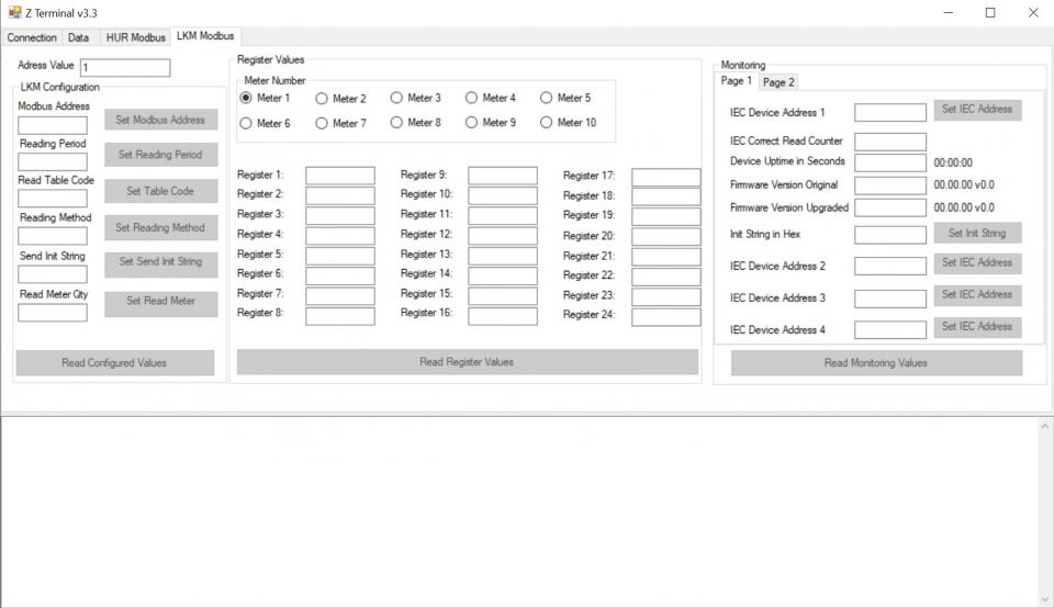
ZTerminal software can be used to read all parameters of LKM devices, alter parameters that are allowed to change and read all registers for all meters connected to LKM devices. This is unoffical software for LKM series of devices and it is an implementation of Modbus commands only.
It supports both Modbus RTU and Modbus TCP ( LKMs connected behind CKL series Modbus TCP to RTU gateway for example) communication.
HUR Series Modbus RTU Remote I/O Devices has capability to upgrade firmware from serial line. This way the user can get latest updates for device operation and also user may also ask for custom changes. Here are some examples:
Firmware upgrade for specific Modbus Register for query
Firmware upgrade to disable switches and work only in one mode
Firmware upgrade to put any feature that user needs
Firmware upgrade procedure need specific firmware file prepared by our company and the firmware upgrade software abcZ software also developed by our company.
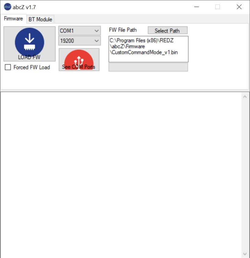
In order to use the software the specific firmware must be selected. After selecting the firmware path by clicking "Select Path" button the firmware can be loaded to device. The device has protection time window 10 seconds after the powered up so the process must be started within 10 seconds after the device powered up.
User can select the correct COM port and click "LOAD FW" button. The software will show the percentage of process visually by process bar in software. The process will take less than a minute and the device will be ready to use with new firmware after an automatic restart.
If somehow the firmware upgrade process is interrupted and upload file has failed, the device will lose firmware and stay in bootloader mode. In that case user can try upgrading the firmware again and this time should mark the "Forced FW Load" check box.
HUR118: 8 Channels 5-275V AC-DC, 100mA Digital Optocoupler Output Modbus RTU Remote IO Device, 1 x RS485, 5-48V (max. 60V) DC Power Input
HUR128: 8 Channels Digital 5Amps 250VAC/30VDC Relay Output Modbus RTU Remote IO Device, 1 x RS485, 5-48V (max. 60V) DC Power Input
HUR218: 8 Channels 5-275V AC-DC, 100mA Digital Optocoupler Output Modbus RTU Remote IO Device, 1 x RS485, 100 - 240V AC (120 – 370V DC), 50Hz to 60Hz AC Power Input
HUR228: 8 Channels Digital 5Amps 250VAC/30VDC Relay Output Modbus RTU Remote IO Device, 1 x RS485, 100 - 240V AC (120 – 370V DC), 50Hz to 60Hz AC Power Input
HUR318: 8 Channels 12-275 AC-DC, 60mA Digital Optocoupler Input Modbus RTU Remote IO Device, 1 x RS485, 5-48V (max. 60V) DC Power Input
HUR418: 8 Channels 12-275 AC-DC, 60mA Digital Optocoupler Input Modbus RTU Remote IO Device, 1 x RS485, 100 - 240V AC (120 – 370V DC), 50Hz to 60Hz AC Power Input
HUR518: 8 Channels 0-10V and 0-20mA Selectable Analog Input Modbus RTU Remote IO Device, 1 x RS485, 5-48V (max. 60V) DC Power Input
HUR555: 5 Channels 4-20mA Analog Output Modbus RTU Remote IO Device, 1 x RS485, 5-48V (max. 60V) DC Power Input
HUR618: 8 Channels 0-10V and 0-20mA Selectable Analog Input Modbus RTU Remote IO Device, 1 x RS485, 100 - 240V AC (120 – 370V DC), 50Hz to 60Hz AC Power Input
HUR655: 5 Channels 4-20mA Analog Output Modbus RTU Remote IO Device, 1 x RS485, 100 - 240V AC (120 – 370V DC), 50Hz to 60Hz AC Power Input
| Model | 5-48V (max. 60V) DC Power input | 90 - 265V AC (100 – 370V DC), 47Hz to 63Hz AC Power Input | 1 x RS485 port | 8 Channel 5-275V AC-DC, 100mA Digital Optocoupler Output | 8 Channel Digital 5Amp. Relay Output | 8 Channel 12-275 AC-DC, 60mA Digital Optocoupler Input | 8 Channel 0-10V and 0-20mA Selectable Analog Input | 5 Channel 4-20mA Analog Output |
| HUR118 | X | X | X | |||||
| HUR128 | X | X | X | |||||
| HUR218 | X | X | X | |||||
| HUR228 | X | X | X | |||||
| HUR318 | X | X | X | |||||
| HUR418 | X | X | X | |||||
| HUR518 | X | X | X | |||||
| HUR555 | X | X | X | |||||
| HUR618 | X | X | X | |||||
| HUR655 | X | X | X |


THIS SITE USES COOKIES
Various types of cookies are used on our website (and on all other digital platforms including mobile applications).
View our new THE INFORMATIVE TEXT ON LPPD AND PRIVACY here.
Google Analytics
Analytical cookies help us to improve our website by collecting and reporting information on its usage.
Google AdWords and Remarketing
We use marketing cookies to help us improve the relevancy of advertising campaigns you receive.
I have read the above articles
 download