Various types of cookies are used on our website (and on all other digital platforms including mobile applications). View our new THE INFORMATIVE TEXT ON LPPD AND PRIVACY here. Google Analytics Analytical cookies help us to improve our website by collecting and reporting information on its usage. Google AdWords ve Remarketing We use marketing cookies to help us improve the relevancy of advertising campaigns you receive.
I have read the above articles
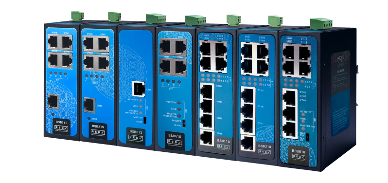
BSB Series Industrial Unmanaged Ethernet Switches are designed for industrial-grade Ethernet, and particularly for facilities of rugged industry and infrastructure. BSB Series Industrial Unmanaged Ethernet Switches are tailored to perform various features, such as wide temperature, wide range power input range... etc. Thus, BSB Series Industrial Unmanaged Ethernet Switches are the best choice for facility management, sewage treatment, power utility, telecommunication, transportation and all other applications that require reliable Ethernet connectivity.
BSB Series has models also with REDZ Broadband Power Line (BPL) communication. BPL link allows device to communicate with full transparent TCP/IP standard over Low Voltage power lines and allows easy connection between TCP/IP based terminals without use of extra cables.
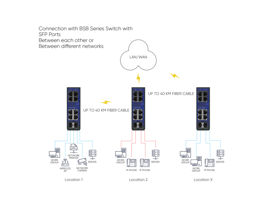
BSB Series has models also with SFP ports for Fiber connectivity. BSB Series with SFP ports offers fiber and ethernet connectivity in same device with plug and play SFP ports. Wide range of SFP modules are available to be used with BSB series.
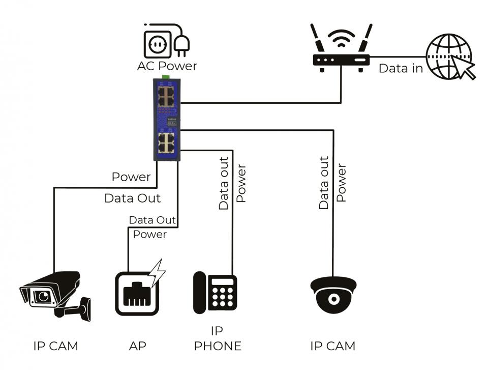
BSB Series has models also with PoE+ ports for Power over Ethernet connectivity. BSB Series Industrial Unmanaged Ethernet Switches with PoE+ ports can power up to 36W device on a single port and total combined power supply is 90W. Additional PoE splitter can be used to separate power and data for field devices.
BSB Series Industrial Unmanaged Ethernet Switches has the versions with and without BPL (Broadband Power Line) Link and with and without SFP Ports.
Supports up to 8 x 10/100Base-T(X) ports
AC or DC wide range power options
Supports Full/Half-Duplex, auto MDI/MDI-X on each port
Wide operating temperature range from -25 to 70 °C AC and -40 to 85 °C DC power input versions
Rugged Metal IP-40 housing design
DIN-Rail mounting
Supports up to 7 x 10/100Base-T(X) ports + 1 x BPL link
Options for wide range 3 phase AC Power Input 110V–240V/50-60Hz or 9-36V DC Power Input
Supports up to 30Mbps PHY rate on BPL with Up to 10 hops and 1000 nodes
Up to 432 sub-carriers from 2 to 28MHz analog bandwidth
Support LDPC-C FEC with 128-bit AES core
Plug and play with Master/Slave selection via switch
Supports 8 x 10/100Base-T(X) ports
Supports 2 x 10/100/1000 SFP Ports
AC or DC wide range power options
Wide operating temperature range from -25 to 70 °C AC and -40 to 85 °C DC power input versions
Rugged Metal IP-40 housing design
Supports 8 x 10/100Base-T(X) ports
Supports PoE+ on all ports
90 Watt Power Supply combined for all ports
Maximum 36 Watt per port
IEEE 802.3AF-2003 and 802.3AT-2009 compliant
Plug-and-play without additional settings
100 - 240V AC (120 – 370V DC), 50Hz to 60Hz AC wide range power input
90Watt Power Supply
Wide operating temperature range from -30 to 80 °C
Rugged Metal IP-40 housing design
DIN-Rail mounting
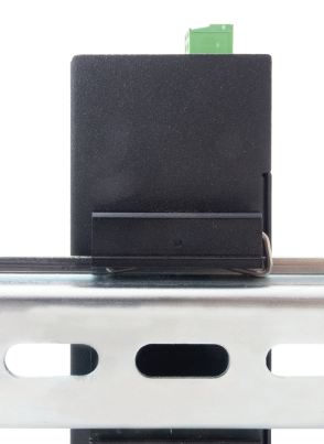
Each switch has a Din-Rail kit on rear panel. The Din-Rail kit helps switch to fix on the Din-Rail. Slant the switch and mount the metal spring to Din-Rail.
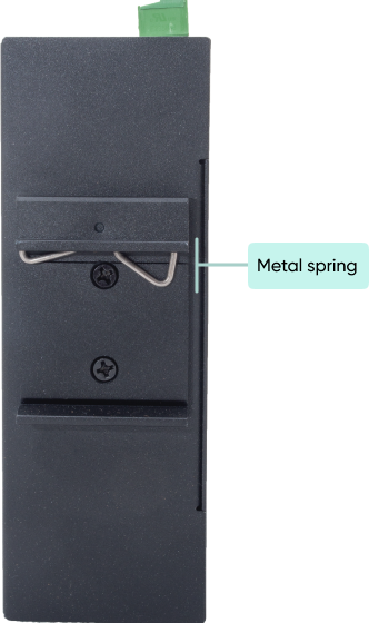
Then Push the switch toward the Din-Rail until you heard a “click” sound.
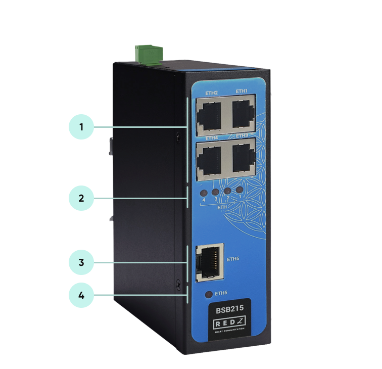
10/100Base-T(X) Ethernet ports 1, 2, 3 and 4.
ETHERNET Activity LEDs for port 1, 2, 3 and 4. Blinks during ethernet activity.
10/100Base-T(X) Ethernet port 5.
ETHERNET Activity LED for port 5. Blinks during ethernet activity.
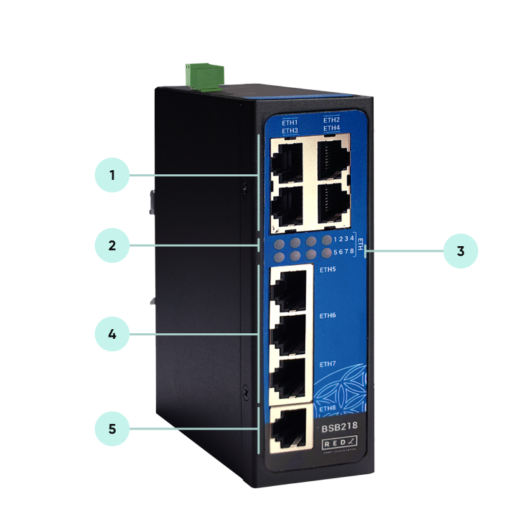
10/100Base-T(X) Ethernet ports 1, 2, 3 and 4.
ETHERNET Activity LEDs for port 1, 2, 3 and 4. Blinks during ethernet activity.
ETHERNET Activity LEDs for port 5, 6, 7 and 8. Blinks during ethernet activity.
10/100Base-T(X) Ethernet ports 5, 6, 7 and 8.
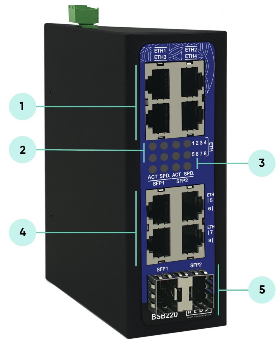
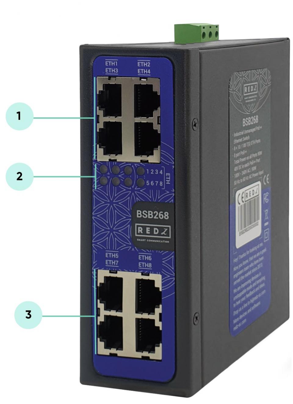
10/100Base-T(X) Ethernet ports 1, 2, 3 and 4.
Supports PoE+ on all ports
90 Watt Power Supply combined for all ports
Maximum 36 Watt per port
ETHERNET Activity LEDs for port 1, 2, 3, 4, 5, 6, 7 and 8. Blinks during ethernet activity.
10/100Base-T(X) Ethernet ports 5, 6, 7 and 8.
Supports PoE+ on all ports
90 Watt Power Supply combined for all ports
Maximum 36 Watt per port
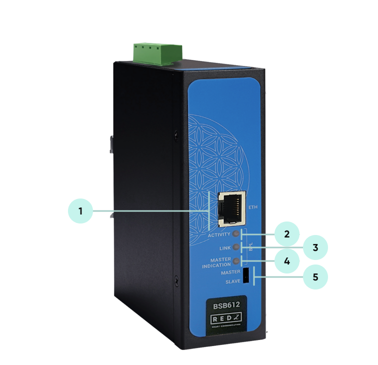
10/100Base-T(X) Ethernet port.
BPL Activity LED. Blinks during BPL & Ethernet activity.
BPL Link LED. LED Turns ON if the link can be established.
Master Indication LED. LED Turns ON if the device is started as “Master” device.
Switch position to select the device as “Master” or “Slave”. Device must be repowered after changing the setting to take into effect.
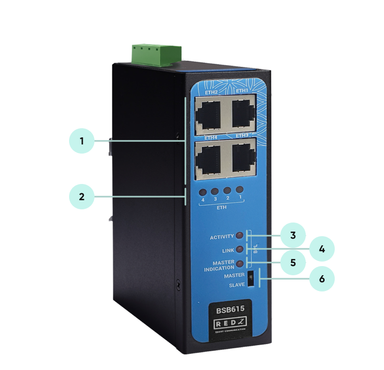
10/100Base-T(X) Ethernet ports 1, 2, 3 and 4.
ETHERNET Activity LEDs for port 1, 2, 3 and 4. Blinks during ethernet activity.
BPL Activity LED. Blinks during BPL & Ethernet activity.
BPL Link LED. LED Turns ON if the link can be established.
Master Indication LED. LED Turns ON if the device is started as “Master” device.
Switch position to select the device as “Master” or “Slave”. Device must be repowered after changing the setting to take into effect.
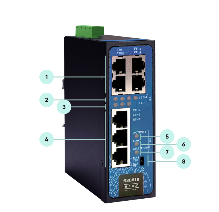
10/100Base-T(X) Ethernet ports 1, 2, 3 and 4.
ETHERNET Activity LEDs for port 1, 2, 3 and 4. Blinks during ethernet activity.
ETHERNET Activity LEDs for port 5, 6, and 7. Blinks during ethernet activity.
10/100Base-T(X) Ethernet ports 5, 6, and 7.
BPL Activity LED. Blinks during BPL & Ethernet activity.
BPL Link LED. LED Turns ON if the link can be established.
Master Indication LED. LED Turns ON if the device is started as “Master” device.
Switch position to select the device as “Master” or “Slave”. Device must be repowered after changing the setting to take into effect.
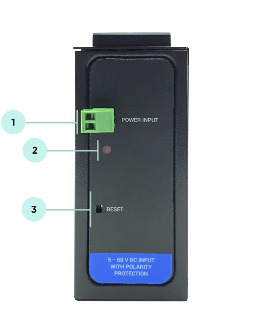
Power Input DC: 5-60V DC. Polarity protected so that the power input can be connected in any direction.
Power LED: Turns ON when there is power in device.
Reset Button: Reset the device.
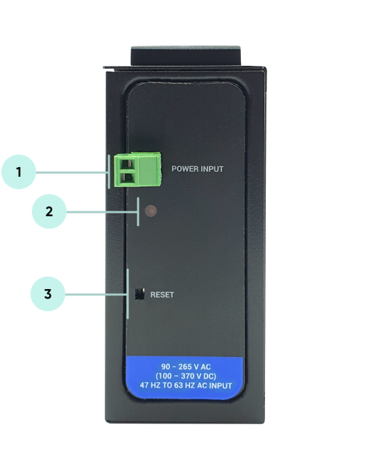
Power Input AC: 90 - 265V AC (100 – 370V DC), 47Hz to 63Hz AC input.
Power LED: Turns ON when there is power in device.
Reset Button: Reset the device.
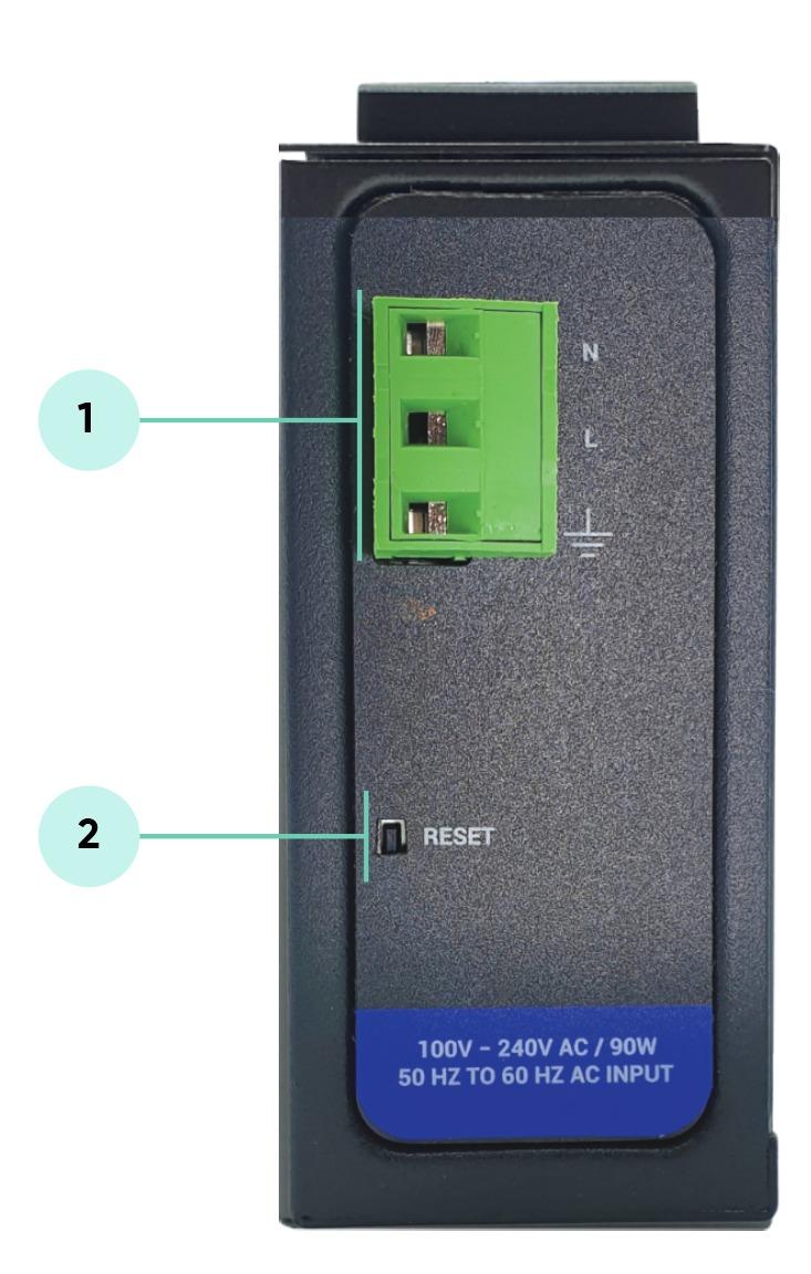
Power Input AC: 100 - 240V AC (120 – 370V DC), 50Hz to 60Hz AC Wide Range Power Input
90Watt Power Supply
Reset Button: Reset the device.
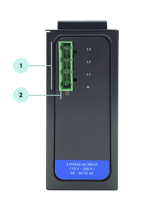
Power Input AC: 3 phase input, 110V–240V/50-60Hz. It is also ok to connect only single phase to the device such as L1-N connection only.
AC Power supply use L1-N only. Phase 2-3 connections are used to BPL signal transmission.
Power LED: Turns ON when there is power in device.

NOTE1 : BPL Model can be purchased in 2 versions:
1. P-N Model: Phase to neutral model (Standart Model). That version gets power from terminal pins 1 and 2 from phase and neutral. It can also transmit data from that pins and other pins usage is optionAl (Ex: Master can be connected to all phases and slaves can be connected to relevant phases)
2. P-P Model: Phase to phase model. That version also gets power from terminal pins 1 and 2 from phase and neutral. Data transmission only done through terminal pins 3 and 4. Phase to phase connection can be done to data transmission pins for better performance.
If not used then phase and neutral can still be connected for data transmission for terminal pins 3 and 4.

NOTE2: BPL Model can be purchased in DC model as well:
This model will be same as "P-P Model"( Phase to phase model) on data connection and gets 9-36V DC power from terminal pins 1 and 2. Data transmission only done through terminal pins 3 and 4.
BSB Series Industrial Unmanaged Ethernet Switches have standard Ethernet ports. According to the link type, the switches use CAT 3, 4, 5, 5e UTP cables to connect to any other network device (PCs, servers, switches, routers, or hubs).
| Cable | Type | Max. Length | Connector |
| 10BASE-T | Cat. 3, 4, 5 100-ohm | UTP 100 m (328 ft) | RJ-45 |
| 100BASE-TX | Cat. 5 100-ohm UTP | UTP 100 m (328 ft) | RJ-45 |
With 100BASE-TX/10BASE-T cable, pins 1 - 2 are used for transmitting data and pins 3 - 6 are used for receiving data.
| Pin Number | Description |
| 1 | TD+ |
| 2 | TD- |
| 3 | RD+ |
| 4 | Not Used |
| 5 | Not Used |
| 6 | RD- |
| 7 | Not Used |
| 8 | Not Used |
Following SFP modules are available to be used with BSB SFP versons
| Model Name | Dexcription | SFP Type | Technical Details | Explanation | How to Use | Cables Used |
| CE-GLC-FE-100FX | 155M, Dual Fiber, Multi Mode, 1310nm, 2KM, Industrial | 100Mbit/s SFP | F2 Multi-mode fiber; LC connector; with black or Beige color coding | LFX (name dependent on manufacturer) – 1310 nm, for a distance up to 2 km | Connect 2 x same device on both device | LC-LC MM Duplex |
| CE-GLC-FE-100LX | 155M, Dual Fiber, SM, 1310nm, 20KM, Industrial | 100Mbit/s SFP | Single-mode fiber, LC connector, with blue color coding | LX – 1310 nm, for distances up to 20 km | Connect 2 x same device on both device | LC-LC SM Duplex |
| GLC-BX-20U | 155M Bidi SFP, 1310nm-TX/1550nm-RX, 20km, LC Port, Industrial | 100Mbit/s SFP | Single-mode fiber, LC connector, Bi-Directional, with blue and yellow color coding | BX (officially BX10) – 1550 nm/1310 nm, Single Fiber Bi-Directional 100 Mbit SFP Transceivers, paired as BX-U (blue) and BX-D (yellow) for uplink and downlink respectively, also for distances up to 20 km. Variations of bidirectional SFPs are also manufactured which higher transmit power versions with link length capabilities up to 20 km. | Connect 1 x U version on 1 device and 1 x D version on other device | LC-LC SM Simplex |
| GLC-BX-20D | 155M Bidi SFP, 1550nm-TX/1310nm-RX, 20km, LC Port, Industrial | 100Mbit/s SFP | ||||
| CE-GLC-T | 10/100M Copper SFP, RJ45 Port, 100M, Industrial | 100Mbit/s SFP | Copper twisted-pair cabling, 8P8C (RJ-45) connector | 100BASE-TX – for distances up to 100m. | Connect 2 x same device on both device | RJ45 Cable |
| GLC-SX-MMD | 1.25G, Dual Fiber, MM, 850nm, 550m, Industrial | 1Gbit/s SFP | 1 Gbit/s multi-mode fiber, LC connector, with black or beige extraction lever | SX – 850 nm, for a maximum of 550 m at 1.25 Gbit/s (gigabit Ethernet). Other multi-mode SFP applications support even higher rates at shorter distances. | Connect 2 x same device on both device | LC-LC MM Duplex |
| CE-GLC-BX-3U | 1.25G Bidi SFP, 1310nm-TX/1550nm-RX, 3km, SC or LC Port, Industrial | 1Gbit/s SFP | 1 to 2.5 Gbit/s single-mode fiber, LC connector, with blue extraction lever | BX (officially BX10) – 1550 nm/1310 nm, Single Fiber Bi-Directional Gigabit SFP Transceivers, paired as BX-U and BX-D for uplink and downlink respectively, also for distances up to 10 km. Variations of bidirectional SFPs are also manufactured which use 1550 nm in one direction, and higher transmit power versions with link length capabilities up to 80 km. | Connect 1 x U version on 1 device and 1 x D version on other device | LC-LC SM Simplex |
| CE-GLC-BX-3D | 1.25G Bidi SFP, 1550nm-TX/1310nm-RX, 3km, SC or LC Port, Industrial | 1Gbit/s SFP | ||||
| CE-GLC-BX-10U | 1.25G Bidi SFP, 1550nm-TX/1310nm-RX, 10km, LC or SC Port, Industrial | 1Gbit/s SFP | ||||
| CE-GLC-BX-10D | 1.25G Bidi SFP, 1550nm-TX/1310nm-RX, 10km, LC or SC Port, Industrial | 1Gbit/s SFP | ||||
| CE-GLC-BX-20U | 1.25G Bidi SFP, 1310nm-TX/1550nm-RX, 20km, LC or SC Port, Industrial | 1Gbit/s SFP | ||||
| CE-GLC-BX-20D | 1.25G Bidi SFP, 1550nm-TX/1310nm-RX, 20km, LC or SC Port, Industrial | 1Gbit/s SFP | ||||
| CE-GLC-BX-40U | 1.25G Bidi SFP, 1310nm-TX/1550nm-RX, 40km, LC or SC Port, Industrial | 1Gbit/s SFP | ||||
| CE-GLC-BX-40D | 1.25G Bidi SFP, 1550nm-TX/1310nm-RX, 40km, LC or SC Port, Industrial | 1Gbit/s SFP | ||||
| CE-GLC-T | 10/100/1000M Copper SFP, RJ45 Port, 100M, Industrial | 1Gbit/s SFP | 1 Gbit/s for copper twisted-pair cabling, 8P8C (RJ-45) connector | 1000BASE-T – these modules incorporate significant interface circuitry for Physical Coding Sublayer recoding and can be used only for gigabit Ethernet because of the specific line code. They are not compatible with (or rather: do not have equivalents for) Fiber Channel. Unlike non-SFP, copper 1000BASE-T ports integrated into most routers and switches, 1000BASE-T SFPs usually cannot operate at 100BASE-TX speeds. | Connect 2 x same device on both device | RJ45 Cable |
| GLC-LH-SMD | 1.25G, Dual Fiber, 1310nm, 10km, Industrial | 1Gbit/s SFP | Single Mode fiber, LC connector | LH – 1310 nm, for a maximum of 10KM at 1.25 Gbit/s (gigabit Ethernet). Other multi-mode SFP applications support even higher rates at shorter distances. | Connect 2 x same device on both device | LC-LC SM Duplex |
| GLC-LH-SMD-20 | 1.25G, Dual Fiber, 1310nm, 20km, Industrial | 1Gbit/s SFP | Single Mode fiber, LC connector | LH – 1310 nm, for a maximum of 10KM at 1.25 Gbit/s (gigabit Ethernet). Other multi-mode SFP applications support even higher rates at shorter distances. | Connect 2 x same device on both device | LC-LC SM Duplex |

NOTE: Multi Mode Duplex should connect same Multi Mode Duplex wavelength, like 850MM should connector MM 850nm, couldn't connect MM 1310.
Single Mode duplex should connect same Single Mode wavelength, SM Duplex 1310 should connect SM 1310 Duplex, couldn't connect SM Duplex 1550NM.
Duplex couldn't connect Simplex BIDI.
Simplex BIDI only connect simplex BIDI U connect D, D couldn't connect D U couldn't connect U.
Single Mode(SM) couldn't connect Multi Mode(MM).
| Pin Number | Data | Power |
| Pin 1 | Rx + | DC + |
| Pin 2 | Rx - | DC + |
| Pin 3 | Tx + | DC- |
| Pin 4 | Unused | Unused |
| Pin 5 | Unused | Unused |
| Pin 6 | Tx - | DC - |
| Pin 7 | Unused | Unused |
| Pin 8 | Unused | Unused |
The small form-factor pluggable (SFP) is a compact, hot-pluggable network interface module used for both telecommunication and data communications applications. An SFP interface on networking hardware is a modular slot for a media-specific transceiver in order to connect a fiber-optic cable or sometimes a copper cable.
The advantage of using SFPs compared to fixed interfaces (e.g. modular connectors in Ethernet switches) is that individual ports can be equipped with any suitable type of transceiver as needed.
- Multi-mode fiber, LC connector, with black or Beige color coding
SX – 850 nm, for a maximum of 550 m
- Multi-mode fiber, LC connector, with blue color coding
FS – 1300 nm, for a distance up to 5 km.
LFX (name dependent on manufacturer) – 1310 nm, for a distance up to 5 km.
Available SFP module from REDZ:
| Model Name | Description | Cable Used |
| CE-GLC-FE-100FX | 155M, Dual Fiber, Multi Mode, 1310nm, 2KM, Industrial | LC-LC MM Duplex |
- Single-mode fiber, LC connector, with blue color coding
LX – 1310 nm, for distances up to 20 km
Available SFP module from REDZ:
| Model Name | Description | Cable Used |
| CE-GLC-FE-100LX | 155M, Dual Fiber, SM, 1310nm, 20KM, Industrial | LC-LC SM Duplex |
EX – 1310 nm, for distances up to 40 km
- Single-mode fiber, LC connector, with green color coding
ZX – 1550 nm, for distances up to 80 km, (depending on fiber path loss)
EZX – 1550 nm, for distances up to 160 km (depending on fiber path loss)
- Single-mode fiber, LC connector, Bi-Directional, with blue and yellow color coding
BX (officially BX10) – 1550 nm/1310 nm, Single Fiber Bi-Directional 100 Mbit SFP Transceivers, paired as BX-U (blue) and BX-D (yellow) for uplink and downlink respectively, also for distances up to 10 km. Variations of bidirectional SFPs are also manufactured which higher transmit power versions with link length capabilities up to 40 km.
Available SFP module from REDZ:
| Model Name | Description | Cable Used |
| GLC-BX-20U | 155M Bidi SFP, 1310nm-TX/1550nm-RX, 20km, LC Port, Industrial | LC-LC SM Simplex |
| GLC-BX-20D | 155M Bidi SFP, 1550nm-TX/1310nm-RX, 20km, LC Port, Industrial | LC-LC SM Simplex |
- Copper twisted-pair cabling, 8P8C (RJ-45) connector
100BASE-TX – for distances up to 100m.
Available SFP module from REDZ:
| Model Name | Description | Cable Used |
| CE-GLC-T | 10/100M Copper SFP, RJ45 Port, 100M, Industrial | RJ45 Cable |
- 1 Gbit/s multi-mode fiber, LC connector, with black or beige extraction lever
SX – 850 nm, for a maximum of 550 m at 1.25 Gbit/s (gigabit Ethernet). Other multi-mode SFP applications support even higher rates at shorter distances.
Available SFP module from REDZ:
| Model Name | Description | Cable Used |
| GLC-SX-MMD | 1.25G, Dual Fiber, MM, 850nm, 550m, Industrial | LC-LC MM Duplex |
- 1.25 Gbit/s multi-mode fiber, LC connector, extraction lever colors not standardized
SX+/MX/LSX (name dependent on manufacturer) – 1310 nm, for a distance up to 2 km. Not compatible with SX or 100BASE-FX. Based on LX but engineered to work with a multi-mode fiber using a standard multi-mode patch cable rather than a mode-conditioning cable commonly used to adapt LX to multi-mode.
- 1 to 2.5 Gbit/s single-mode fiber, LC connector, with blue extraction lever
LX – 1310 nm, for distances up to 10 km (originally, LX just covered 5 km and LX10 for 10 km followed later)
LH – 1310 nm, for a maximum of 20 km. Other multi-mode SFP applications support even higher rates at shorter distances.
| Model Name | Description | Cable Used |
| GLC-LH-SMD | 1.25G, Dual Fiber, 1310nm, 10km, Industrial | LC-LC SM Duplex |
| GLC-LH-SMD-20 | 1.25G, Dual Fiber, 1310nm, 20km, Industrial | LC-LC SM Duplex |
EX – 1310 nm, for distances up to 40 km
ZX – 1550 nm, for distances up to 80 km (depending on fiber path loss), with green extraction lever (see GLC-ZX-SM1)
EZX – 1550 nm, for distances up to 160 km (depending on fiber path loss)
BX (officially BX10) – 1490 nm/1310 nm, Single Fiber Bi-Directional Gigabit SFP Transceivers, paired as BX-U and BX-D for uplink and downlink respectively, also for distances up to 10 km. Variations of bidirectional SFPs are also manufactured which use 1550 nm in one direction, and higher transmit power versions with link length capabilities up to 80 km.
Available SFP module from REDZ:
| Model Name | Description | Cable Used |
| CE-GLC-BX-3U | 1.25G Bidi SFP, 1310nm-TX/1550nm-RX, 3km, SC or LC Port, Industrial | LC-LC SM Simplex |
| CE-GLC-BX-3D | 1.25G Bidi SFP, 1550nm-TX/1310nm-RX, 3km, SC or LC Port, Industrial | LC-LC SM Simplex |
| CE-GLC-BX-10U | 1.25G Bidi SFP, 1550nm-TX/1310nm-RX, 10km, LC or SC Port, Industrial | LC-LC SM Simplex |
| CE-GLC-BX-10D | 1.25G Bidi SFP, 1550nm-TX/1310nm-RX, 10km, LC or SC Port, Industrial | LC-LC SM Simplex |
| CE-GLC-BX-20U | 1.25G Bidi SFP, 1310nm-TX/1550nm-RX, 20km, LC or SC Port, Industrial | LC-LC SM Simplex |
| CE-GLC-BX-20D | 1.25G Bidi SFP, 1550nm-TX/1310nm-RX, 20km, LC or SC Port, Industrial | LC-LC SM Simplex |
| CE-GLC-BX-40U | 1.25G Bidi SFP, 1310nm-TX/1550nm-RX, 40km, LC or SC Port, Industrial | LC-LC SM Simplex |
| CE-GLC-BX-40D | 1.25G Bidi SFP, 1550nm-TX/1310nm-RX, 40km, LC or SC Port, Industrial | LC-LC SM Simplex |
1550 nm 40 km (XD), 80 km (ZX), 120 km (EX or EZX)
SFSW – single-fiber single-wavelength transceivers, for bi-directional traffic on a single fiber. Coupled with CWDM, these double the traffic density of fiber links.
Coarse wavelength-division multiplexing (CWDM) and dense wavelength-division multiplexing (DWDM) transceivers at various wavelengths achieving various maximum distances. CWDM and DWDM transceivers usually support link distances of 40 km, 80 km and 120 km.
- 1 Gbit/s for copper twisted-pair cabling, 8P8C (RJ-45) connector
1000BASE-T – these modules incorporate significant interface circuitry for Physical Coding Sublayer recoding and can be used only for gigabit Ethernet because of the specific line code. They are not compatible with (or rather: do not have equivalents for) Fiber Channel. Unlike non-SFP, copper 1000BASE-T ports integrated into most routers and switches, 1000BASE-T SFPs usually cannot operate at 100BASE-TX speeds.
Available SFP module from REDZ:
| Model Name | Description | Cable Used |
| CE-GLC-T | 10/100/1000M Copper SFP, RJ45 Port, 100M, Industrial | RJ45 Cable |
BSB Series Industrial Unmanaged Ethernet Switches connections vary based on with and without BPL (Broadband Power Line ) Link versions.
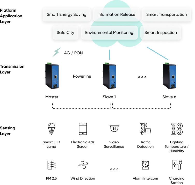
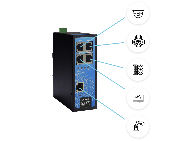
| CAT5 Based System | BPL Link Based System | |
| Media | CAT5 | Power Line |
| Bandwidth | 100Mbps | Up to 30Mbps |
| Re-Wire | Yes | No, Using existing Power Line |
| Span | <100m | <600m |
| Multiple Nodes | N/A | Up to 10 hops/1000 nodes |
| Encryption | Yes, but difficult to configure | Yes, Plug & Play |
| Installment | Difficult | Easy, simply user power line |
| Installment Cost | High | Low |
| Total Cost | High | Low |

NOTE1 : BPL Model can be purchased in 2 versions:
1. P-N Model: Phase to neutral model (Standart Model). That version gets power from terminal pins 1 and 2 from phase and neutral. It can also transmit data from that pins and other pins usage is optional (Ex: Master can be connected to all phases and slaves can be connected to relevant phases)
2. P-P Model: Phase to phase model. That version also gets power from terminal pins 1 and 2 from phase and neutral. Data transmission only done through terminal pins 3 and 4. Phase to phase connection can be done to data transmission pins for better performance.
If not used then same phase and neutral connected to power input can still be connected for data transmission for terminal pins 3 and 4.

NOTE2: BPL Model can be purchased in DC model as well:
This model will be same as "P-P Model"( Phase to phase model) on data connection and gets 9-36V DC power from terminal pins 1 and 2. Data transmission only done through terminal pins 3 and 4.
Default firmware for Broadband Power Line (BPL) version BSB series shipped with multi hop (mesh network) functionality. If needed that firmware can be changed in the field.

NOTE: Devices can be order with desired functionality during order. It is not advised to change firmware in field unless it is a must, since mistakes during that procedure may make device unreachable.
Here are steps to achieve that:
Here is a video for application:

NOTE1 : BPL Model can be purchased in 2 versions:
1. P-N Model: Phase to neutral model (Standart Model). That version gets power from terminal pins 1 and 2 from phase and neutral. It can also transmit data from that pins and other pins usage is optionAl (Ex: Master can be connected to all phases and slaves can be connected to relevant phases)
2. P-P Model: Phase to phase model. That version also gets power from terminal pins 1 and 2 from phase and neutral. Data transmission only done through terminal pins 3 and 4. Phase to phase connection can be done to data transmission pins for better performance.
If not used then phase and neutral can still be connected for data transmission for terminal pins 3 and 4.

NOTE2: BPL Model can be purchased in DC model as well:
This model will be same as "P-P Model"( Phase to phase model) on data connection and gets 12V DC power from terminal pins 1 and 2. Data transmission only done through terminal pins 3 and 4.
BSB series BPL switches can work without hops. This is tree based communication and there will be 1 master and many slaves and all slaves will be connected to master directly (without hops).

NOTE: No hop version needs special firmware and user can get that firmware from our company and update devices in field.
There is also another option for no hop firmware, devices can be paired so that there can be many masters and many slaves in same power network. This can help to isolate BPL connections from each other.
Here are steps to achieve that:
Here is a video for application:
Here is a video for physicall application:
Here is a video for speed test:
Here is an example communication video for BSB615 DC powered models
Here is an example communication video for BSB618 DC powered models
BSB115: Industrial Unmanaged Ethernet Switch, 5 x 10/100 T(x) ETH ports, 5- 48 (max. 60V) DC Power Input
BSB118: Industrial Unmanaged Ethernet Switch, 8 x 10/100 T(x) ETH ports, 5- 48 (max. 60V) DC Power Input
BSB120: Industrial Unmanaged Ethernet Switch, 8 x 10/100 T(x) ETH ports and 2 x SFP Uplink Ports, 5- 48 (max. 60V) DC Power Input
BSB215: Industrial Unmanaged Ethernet Switch, 5 x 10/100 T(x) ETH ports, 100 - 240V AC (120 – 370V DC), 50Hz to 60Hz AC Power Input
BSB218: Industrial Unmanaged Ethernet Switch, 8 x 10/100 T(x) ETH ports, 100 - 240V AC (120 – 370V DC), 50Hz to 60Hz AC Power Input
BSB220: Industrial Unmanaged Ethernet Switch, 8 x 10/100 T(x) ETH ports and 2 x SFP Uplink Ports, 100 - 240V AC (120 – 370V DC), 50Hz to 60Hz AC Power Input
BSB268: Industrial Unmanaged PoE+ Ethernet Switch, 8 x 10/100 T(x) ETH ports and all Ports Support PoE+, 100 - 240V AC (120 – 370V DC), 50Hz to 60Hz AC Wide Range Power Input, 90 Watt Power Supply combined for all ports
BSB612 - PN - AC: Industrial Unmanaged Ethernet Switch, 1 x 10/100 T(x) ETH ports + 1 x BPL (Broadband Power Line) Link, 3 Phase AC Power Input, 110V–240V/50-60Hz, Phase to Neutral Connection on Data Terminals
BSB612 - PP - AC: Industrial Unmanaged Ethernet Switch, 1 x 10/100 T(x) ETH ports + 1 x BPL (Broadband Power Line) Link, AC Power Input 110V–240V/50-60Hz, Phase to Neutral and Phase to Phase Connection on Data Terminals
BSB612 - PP - DC: Industrial Unmanaged Ethernet Switch, 1 x 10/100 T(x) ETH ports + 1 x BPL (Broadband Power Line) Link, 9-36V DC Power Input, Phase to Neutral and Phase to Phase Connection on Data Terminals
BSB615 - PN - AC: Industrial Unmanaged Ethernet Switch, 4 x 10/100 T(x) ETH ports + 1 x BPL (Broadband Power Line) Link, 3 Phase AC Power Input, 110V–240V/50-60Hz, Phase to Neutral Connection on Data Terminals
BSB615 - PP - AC: Industrial Unmanaged Ethernet Switch, 4 x 10/100 T(x) ETH ports + 1 x BPL (Broadband Power Line) Link, AC Power Input 110V–240V/50-60Hz, Phase to Neutral and Phase to Phase Connection on Data Terminals
BSB615 - PP - DC: Industrial Unmanaged Ethernet Switch, 4 x 10/100 T(x) ETH ports + 1 x BPL (Broadband Power Line) Link, 9-36V DC Power Input, Phase to Neutral and Phase to Phase Connection on Data Terminals
BSB618 - PN - AC: Industrial Unmanaged Ethernet Switch, 7 x 10/100 T(x) ETH ports + 1 x BPL (Broadband Power Line) Link, 3 Phase AC Power Input, 110V–240V/50-60Hz, Phase to Neutral Connection on Data Terminals
BSB618 - PP - AC: Industrial Unmanaged Ethernet Switch, 7 x 10/100 T(x) ETH ports + 1 x BPL (Broadband Power Line) Link, AC Power Input 110V–240V/50-60Hz, Phase to Neutral and Phase to Phase Connection on Data Terminals
BSB618 - PP - DC: Industrial Unmanaged Ethernet Switch, 7 x 10/100 T(x) ETH ports + 1 x BPL (Broadband Power Line) Link, 9-36V DC Power Input, Phase to Neutral and Phase to Phase Connection on Data Terminals
| Model | 5-48V (Max.60V) DC Power input | 100 - 240V AC (120 – 370V DC), 50Hz to 60Hz AC Power Input | 3 Phase AC Power input, 110V–240V/50-60Hz AC Power Input | 8 x 10/100 T(x) ETH Ports | 7 x 10/100 T(x) ETH Ports | 5 x 10/100 T(x) ETH Ports | 4 x 10/100 T(x) ETH Ports | 1 x 10/100 T(x) ETH Ports | BPL (Broadband Power Line) Link | 2 x SFP Uplink Ports | PoE+, 90 Watt Power Supply combined for all ports |
| BSB115 | X | X | |||||||||
| BSB118 | X | X | |||||||||
| BSB120 | X | X | X | ||||||||
| BSB215 | X | X | |||||||||
| BSB218 | X | X | |||||||||
| BSB220 | X | X | X | X | |||||||
| BSB268 | X | X | X | ||||||||
| BSB612 | X | X | X | ||||||||
| BSB615 | X | X | X | ||||||||
| BSB618 | X | X | X |
THIS SITE USES COOKIES
Various types of cookies are used on our website (and on all other digital platforms including mobile applications).
View our new THE INFORMATIVE TEXT ON LPPD AND PRIVACY here.
Google Analytics
Analytical cookies help us to improve our website by collecting and reporting information on its usage.
Google AdWords and Remarketing
We use marketing cookies to help us improve the relevancy of advertising campaigns you receive.
I have read the above articles